I just used the LT model. Any will do , lm833 fits my pads well , cost $1.07.
Op-amp just adjusts CCS's , quality is not critical.
OS
Op-amp just adjusts CCS's , quality is not critical.
OS


I noticed the RED LED in the SMD parts list doesn't have any Vf vs If curves in the datasheet, its specified at 1.7-2.3v @ 20mA, there's no way to determine what the Vf is at say 3.4mA (Spooky Vas current).
I discovered Wurth provide ltspice models for their LED's. For RED try using a p/n 150120RS75000.
https://www.we-online.com/en/components/products/WL-SMCW#/articles/WL-SMCW-1206
You can download the models from their website or you can now find them in the ltspice component/contrib/wurth folder.
I discovered Wurth provide ltspice models for their LED's. For RED try using a p/n 150120RS75000.
https://www.we-online.com/en/components/products/WL-SMCW#/articles/WL-SMCW-1206
You can download the models from their website or you can now find them in the ltspice component/contrib/wurth folder.
"Sorry, we only accept Gerber RS274X format file"
Hi Pete,jlcpcb don't accept lay6 files 😢
Not the PCBWAY."We support gerber file in format of RS-274-X."
You need to export gerbers.🙏
Hi Pete,jlcpcb don't accept lay6 files 😢
Not the PCBWAY."We support gerber file in format of RS-274-X."
You need to export gerbers.🙏
Last edited:
Yes , I outputted the gerbers for slewmaster.
I want to review the artwork before I do.
Sprint outputs RS-274-X.
Yup , that model shows as "seoul semi" @ 2.1Vf. just needs R14/21 changed from 390 to 620R.
NO issue designing around a different part. Most modern red LED's are 2V. The olde dim GaAS were 1.7Vf.
Then , there is the Cascodes , you will lose another 1/2V max VAS output swing.
I want to review the artwork before I do.
Sprint outputs RS-274-X.
That red is 2V. The red's are quite important for any CCS. A 2V red would require a higher Re at the CCS tranny (to get 3.4mA).I noticed the RED LED in the SMD parts list doesn't have any Vf vs If curves in the datasheet, its specified at 1.7-2.3v @ 20mA, there's no way to determine what the Vf is at say 3.4mA (Spooky Vas current).
I discovered Wurth provide ltspice models for their LED's. For RED try using a p/n 150120RS75000.
https://www.we-online.com/en/components/products/WL-SMCW#/articles/WL-SMCW-1206
You can download the models from their website or you can now find them in the ltspice component/contrib/wurth folder.
Yup , that model shows as "seoul semi" @ 2.1Vf. just needs R14/21 changed from 390 to 620R.
NO issue designing around a different part. Most modern red LED's are 2V. The olde dim GaAS were 1.7Vf.
Then , there is the Cascodes , you will lose another 1/2V max VAS output swing.
Last edited:
OS,
Tis a shame that you continue to use sprint but I can look at your fab files if you would like, I'll sign the NDA 🙂
If I had more time it would be nice to get these designs setup in kicad, which I need to learn one day, just for the fun of it, so many more can play along.
There are side benifits, you have help building a parts database, libraries, the things that make a pcb design machine sing.
You where given my Orcad my design environment, did you lose the CD?, many of the parts you are using are in my libraries, I even have them in stock. Its so handy to have schematic parts come from a database, so boms get generated automatically, loaded into Mouser project manager automatically, the monkey work is done by the computers. AI ain't going to do that for you any time soon 🙂
I have a design that I have working in another topology, Pioneer SX-1250, awh-048 power amp module. The original design is old,
I have it in ltspice sim if you want to take a look. Its done in tht as close to origin.
Since the physical layout is done in tht already. There is not much room for all those parts you are using in tht.
I could change the front end to using one of your smt designs, name which one? or send me the sim file to use as my reference
A couple of catches
1) the front end has a separate regulated supply +/-65V, unreg is +-70V no-load
2) You get to review the layout, you can even pick the passives
3) The OPS is remote, so I have to stick with the original cabling and device package TO-3, right now I am using MJ2119x,
but it is something I am willing to try out. It will be done in Orcad
Take care
Rick
Attachments
Last edited:
Yes , I will. Not make the mistake of shoddy BOM's/no build guide.
Designing the circuits and Sprint layout are "a labor of love' , can't be rushed.
I'm gonna stop with 3 IPS's (Spooky , Hellraiser , and definite Symasui). Review all pads and pinouts for perfection.
The 2 through-hole boards are perfect , I'll document them first.
SMD has just so many options as compared to TH. .1uF caps are in 3 case styles , dual BJT's have 6 case styles with different
pinout for each. High voltage BJT's have the emitters as the middle pins LV (BCxxx) has bases in the middle. There are
Japanese 5 - pin SOT-6 with common emitters made for audio.
Looked up that 620R CCS resistor .... thin film/thick film/0805/1206/2010 ... damn !
I "supersized" some SMD placement pads to accommodate multiple packages. With SMD , I have extra room.
Symasui , I might make it 50 X 60mm , and still have room for a big T-H electro BP 47u@50V cap and another 4.7u for the main
cascode decoupling.
I made all .1u 100V decoupling caps 1206 , 2.2u servo caps 1206 , and regulator caps 22u 25V 1825 plus the led's/diodes all 1206.
You can get away with placing 2010/1206 on 1825 pads. You can also do 0805's on a 1206.
I settled for all SOP-6 and 8 for op-amps and dual packages .
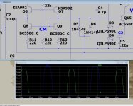
Finished the SYMSASUI testing. Can't really get better (below).
80PPB ! is overkill but expected at 120db OL gain.
OS
Designing the circuits and Sprint layout are "a labor of love' , can't be rushed.
I'm gonna stop with 3 IPS's (Spooky , Hellraiser , and definite Symasui). Review all pads and pinouts for perfection.
The 2 through-hole boards are perfect , I'll document them first.
SMD has just so many options as compared to TH. .1uF caps are in 3 case styles , dual BJT's have 6 case styles with different
pinout for each. High voltage BJT's have the emitters as the middle pins LV (BCxxx) has bases in the middle. There are
Japanese 5 - pin SOT-6 with common emitters made for audio.
Looked up that 620R CCS resistor .... thin film/thick film/0805/1206/2010 ... damn !
I "supersized" some SMD placement pads to accommodate multiple packages. With SMD , I have extra room.
Symasui , I might make it 50 X 60mm , and still have room for a big T-H electro BP 47u@50V cap and another 4.7u for the main
cascode decoupling.
I made all .1u 100V decoupling caps 1206 , 2.2u servo caps 1206 , and regulator caps 22u 25V 1825 plus the led's/diodes all 1206.
You can get away with placing 2010/1206 on 1825 pads. You can also do 0805's on a 1206.
I settled for all SOP-6 and 8 for op-amps and dual packages .
Finished the SYMSASUI testing. Can't really get better (below).
80PPB ! is overkill but expected at 120db OL gain.
OS
That amp of yours is just about "HH" audio's front end. They replaced Q11 with a diode. Add the mirror to the LTP = 10X + reduction in the THD.OS,
Tis a shame that you continue to use sprint but I can look at your fab files if you would like, I'll sign the NDA 🙂
If I had more time it would be nice to get these designs setup in kicad, which I need to learn one day, just for the fun of it, so many more can play along.
There are side benifits, you have help building a parts database, libraries, the things that make a pcb design machine sing.
You where given my Orcad my design environment, did you lose the CD?, many of the parts you are using are in my libraries, I even have them in stock. Its so handy to have schematic parts come from a database, so boms get generated automatically, loaded into Mouser project manager automatically, the monkey work is done by the computers. AI ain't going to do that for you any time soon 🙂
I have a design that I have working in another topology, Pioneer SX-1250, awh-048 power amp module. The original design is old,
I have it in ltspice sim if you want to take a look. Its done in tht as close to origin.
Since the physical layout is done in tht already. There is not much room for all those parts you are using in tht.
I could change the front end to using one of your smt designs, name which one? or send me the sim file to use as my reference
A couple of catches
1) the front end has a separate regulated supply +/-65V, unreg is +-70V no-load
2) You get to review the layout, you can even pick the passives
3) The OPS is remote, so I have to stick with the original cabling and device package TO-3, right now I am using MJ2119x,
but it is something I am willing to try out. It will be done in Orcad
Take care
Rick
Compensate it with 2-pole (move the poles around) get another 10X. SX1250 is the same , why did they not add the mirror ?
It's like building a "blameless" without the Darlington VAS and current sources.
OS
Who's "HH" audio's front end?
why did they not add the mirror ? To save a dime?
Bob Cordell asked why did they not use a LTP current source and what's D6 function? I dunno, save another dime.
I am looking at your Symasui 2.0 in sim, upadating the sim based on your latest revsion?
is BC560C the same as BC860C?
If you stick with sot-23 you have lots of options, common pin out. if you use the smt duals lots of package options.
Have to keep an eye on limited Pd on these smt parts
Notice that Pioneer has gain of x42
https://www.hhelectronics.com/products/instrument/install-sound They are like the British "Peavey" to us. Prosound
and studio equipment. V200 - V800 is an amp they made 1/2 million of them , sold em' worldwide. (below V" series).
None of em' blow out , they are a collectors item from the 80's.
- BC860 / 850 is higher voltage than 560/550 , same <5Cob 100mhz Ft. BC550 is 3X the Ft , lower current and voltage.
We Cascoded .... my designs rarely exceed 20V for BCxxx.
I use BC807/817 even as it's only 100mhz , but low (2pF Cob) , we are just doing audio.
TL072 is the internal op-amp equivalent of this topology. Old ones were FET/BJT , new ones are all MOS.
Symasui would be perfect with FET's for LTP !
OS
and studio equipment. V200 - V800 is an amp they made 1/2 million of them , sold em' worldwide. (below V" series).
None of em' blow out , they are a collectors item from the 80's.
- BC860 / 850 is higher voltage than 560/550 , same <5Cob 100mhz Ft. BC550 is 3X the Ft , lower current and voltage.
We Cascoded .... my designs rarely exceed 20V for BCxxx.
I use BC807/817 even as it's only 100mhz , but low (2pF Cob) , we are just doing audio.
To fake a real BJT's Vf , and save a part ?what's D6 function
TL072 is the internal op-amp equivalent of this topology. Old ones were FET/BJT , new ones are all MOS.
Symasui would be perfect with FET's for LTP !
OS
Attachments
Spooky is full done - "SPOOKYAMP V2.1 PACKAGE.zip" is at the first post.
I need more eyes to compare the layout to the schema.
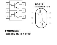
The hard part is the dissimilar pinouts of Q3/4 - 9/10 (cascodes) ... vs. Q5/6 - 7/8 (LTP's).
(Below) are the 2 pinouts for the FMBMxxxx and BC807/817 dual packages.
I actually got it right on the PCB , but the spooky schema had the CCS's wrong ... they should be Q11/12.
Regulators , CCS's , and VAS did not stress me like the differentials.
I'm 99% sure it is right and will work , but not 100%.😒
OS
I need more eyes to compare the layout to the schema.
The hard part is the dissimilar pinouts of Q3/4 - 9/10 (cascodes) ... vs. Q5/6 - 7/8 (LTP's).
(Below) are the 2 pinouts for the FMBMxxxx and BC807/817 dual packages.
I actually got it right on the PCB , but the spooky schema had the CCS's wrong ... they should be Q11/12.
Regulators , CCS's , and VAS did not stress me like the differentials.
I'm 99% sure it is right and will work , but not 100%.😒
OS
Attachments
EF3,power board and Spooky are prime time now. Bom's should be quick. Mouser labels the PDF's with OEM part # , I add device data.
Everything I physically designed for , I have the PDF collection !
VAS pads are smaller than optimal - I won't waste 1/3 the PCB for thermal.
I calculated a worst case 180V DC @ 4mA collector current - .7W. That's for DC , real world each device would see full rail minus the cascode
voltages 1/2 cycle. Should be under .5W. All these SMD (SOT-89) VAS devices are rated 1.2 - 2 W with just the minimum landings. I don't have to use
25mm squared ... here they are rated 3 - 5 W.
I'm most likely overkill for any resistors 1/2W ones just see .2W @ 80V rails. VAS LED ones combined (trimmer + resistor just .54W).
Creepage is easy on most of the IPS's , just 11.4V for everything but the VAS. Glad I designed it that way.
I am surprised by the 160-180V SMD devices , SSOT-6 leads are at half recommended creepage for that voltage. Are they accounting
for the solder mask as insulation ? UL 840 IEC 60664-1 spec does have a table for that. Calculator shows .3mm for masked 180V.
Not many places on these boards where you have rail to rail in close proximity .
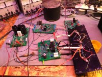
Here's how it will look .... IPS can also be mounted at a right angle for a 2U enclosure ... or replacing the amp in an E- waste enclosure.
OS
Everything I physically designed for , I have the PDF collection !
VAS pads are smaller than optimal - I won't waste 1/3 the PCB for thermal.
I calculated a worst case 180V DC @ 4mA collector current - .7W. That's for DC , real world each device would see full rail minus the cascode
voltages 1/2 cycle. Should be under .5W. All these SMD (SOT-89) VAS devices are rated 1.2 - 2 W with just the minimum landings. I don't have to use
25mm squared ... here they are rated 3 - 5 W.
I'm most likely overkill for any resistors 1/2W ones just see .2W @ 80V rails. VAS LED ones combined (trimmer + resistor just .54W).
Creepage is easy on most of the IPS's , just 11.4V for everything but the VAS. Glad I designed it that way.
I am surprised by the 160-180V SMD devices , SSOT-6 leads are at half recommended creepage for that voltage. Are they accounting
for the solder mask as insulation ? UL 840 IEC 60664-1 spec does have a table for that. Calculator shows .3mm for masked 180V.
Not many places on these boards where you have rail to rail in close proximity .
Here's how it will look .... IPS can also be mounted at a right angle for a 2U enclosure ... or replacing the amp in an E- waste enclosure.
OS
Attachments
Last edited:
Symasui is almost done , next is hellraiser (which I lost).
i'm going to make a through-hole version of symasui.
I love simulating Symasui . By moving the 2 poles around in the compensation (C6,7 + R19),
I can truly get to the point where LT can't even measure the distortion. NO other simulation of mine
can do this.
I added D5/D6 as a clamping mechanism for oversaturation. In this topology is easy to implement this with
only .5PPM penalty. With out this clamp the VAS saturates with 50mA pulses. The BC817's might handle this ,but
it is too close to the limit. D5/6 limits Ie to 20mA. Still measures .00008% @ 20Khz in normal mode.
OS
Attachments

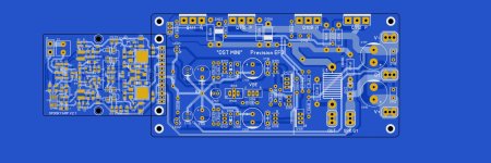
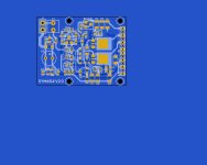
It's done ... time to OCD it !
Such nice short direct traces .... I am confident this will beat the Wolverine.
Device quality will be the deciding factor here.
Offset trim is in the "classic" way. Trim a few ohms LTP Re to zero the output.
Most Bourn SMD trimmers are 5 turn , just a 1/4 turn to compensate for that 1% Hfe
difference in these integrated dual PNP BJT's (BC807DS).
OS
Attachments
- Home
- Amplifiers
- Solid State
- Spooky and Hellraiser SMD 60W amps (Wolverine compatible IPS)