There will only be the forward voltage of the LED across C4 so it'll see under 5V. An MKP would be good there if you have the space.
This doesn't need to be a non-polar cap. It will see a steady 3.15Vdc regulated by the LED. Electrolytic would be fine there but the capacitor snobs might not like it.
Does the Q104 transistor need to be put on a heat sink as is what I could see in one of the builds with extended wiring?View attachment 1268131
I assembly it, ips is infidel light bulb test is ok however I cannot set bias, no current flow through output transitors. Can we test ops and ips separately?
Anyone @chat72 who built this amp successfully can chime in before I finish soldering my boards. Also I am planning to use MJL3281A and MJL1302 transistors as I have few spares with me instead of the TTC/TTA from the BOM.Does the Q104 transistor need to be put on a heat sink as is what I could see in one of the builds with extended wiring?
Thanks

Thanks @jwilhelm for the confirmation, any idea about the usage of MJL transistors?Q104 does need to be mounted on the main heatsink.
Gain is set by the voltage divider made up of R21 and R22. 27k(R22) + 1k(R21) / 1k(R21) = 28 x gain. This the pretty much the industry standard for high power amplifiers. If you want to alter the gain, change R22 accordingly. Stability of the amplifier may be affected if this ratio is changed by much though.
Another option is to just add a voltage divider to the input.
Another option is to just add a voltage divider to the input.
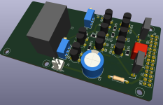
I have a request for symasui PCB which I made it myself using schematic in post 590, here is zip file containing Kicad and Gerber. I build it and test it, it runs OK with no problem but I did not use oscilloscope to probe it.
hi,
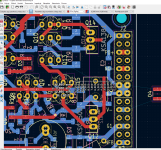
below is "my iteration" of SYMASUY layout. it's based on chat72 work. i've added BOM and made new layout (for my liking).
i'll be ordering PCBs soon, so i you spot any issues pls let me know;
not sure about C6/C7/C10 capacitors, i'm using c0g type, but shouldn't i use MIKA ones? for C4 PET type, maybe x7r would be better option?
track width is another story ... but will see what you think about that 🙂
holes layout allows mounting on Wolverine OPS boards
Gain is set by the voltage divider made up of R21 and R22. 27k(R22) + 1k(R21) / 1k(R21) = 28 x gain. This the pretty much the industry standard for high power amplifiers. If you want to alter the gain, change R22 accordingly. Stability of the amplifier may be affected if this ratio is changed by much though.
so for GAIN of 16 changing R21 to 1.8k will be enough?
Attachments
"so for GAIN of 16 changing R21 to 1.8k will be enough?"
That would set the gain to 16x but the amp would likely be unstable. That's a big change.
At high frequencies the phase of the amplifer will shift and cause the feedback to turn positive, creating an oscillator (aka bomb!). The feedback resistors combined with C8/9 create a low pass filter preventing it from amplifying the positive feedback (this is a very simplified explaination, there's more at play here). The stability of the amp would need to be re-simulated.
Also the impedance of the input nodes (Q5 and Q6 base) should match. R1 and R2 are 1k and 27k as are R21 and R22, so R1 would need to be changed as well.
Last edited:
.... Ok
Then it's not that easy 😉
So we're talking about 10-20% gain change rather than 50%. Correct?
Then it's not that easy 😉
So we're talking about 10-20% gain change rather than 50%. Correct?
Hello,
I'm looking for layouts, for Hellraiser and Spooky Amp, without SMD´s.
Can anyone help me?
Thank you
Gerd
I'm looking for layouts, for Hellraiser and Spooky Amp, without SMD´s.
Can anyone help me?
Thank you
Gerd
Jkuetemann posted some gerber files in the Slewmaster Group Buy thread. https://www.diyaudio.com/community/threads/slewmaster-project-boards.257057/ The index in th first post isn't working so you will need to dig for them.
so for GAIN of 16 changing R21 to 1.8k will be enough?
Out of curiosity I copied your posted Symasui front-end to LTspice, coupled with a 3EF output stage. The amp will remain stable with R21 at 1k8 for a gain of 16. The loop gain plot shows a phase margin of about 40 degrees, slightly better than what would be with R21 at 1K or gain of 28 (thanks to the TMC compensation). There is a decrease of gain margin from the plentiful 18db to a still more than decent 13 db. I'd say worth a try.
Attachments
- Home
- Amplifiers
- Solid State
- Spooky and Hellraiser SMD 60W amps (Wolverine compatible IPS)