yes , and the hh ips can run the ef3. surprised you know of it .... it ran English vfet ops's. cool.
btw ,did you know you can run floppy cable connectors from ips/ops , put the ips anywhere in the case ??
I have bigger heatsinks than you , but i'm mounting my power supply boards+OPS on the heatsinks , ips
will be at the rear( next to the input jacks). PASS amps do this (flat cables).
OS
btw ,did you know you can run floppy cable connectors from ips/ops , put the ips anywhere in the case ??
I have bigger heatsinks than you , but i'm mounting my power supply boards+OPS on the heatsinks , ips
will be at the rear( next to the input jacks). PASS amps do this (flat cables).
OS
Last edited:

I think D4 is backwards?Just for fun, HH-simple IPS, all THT Semi, mini MELF=1206 SMD resistors +THT parts only 5cmx5cm board.
hi
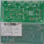
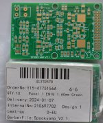
if anyone is interested i have 4 or 6 boards to resell (depending on how many will use myself) at cost of manufacturing + shipping+taxes.
arcwelder mini is HASL finish and 2oz copper; Spookyamp IPS is 1oz copper and ENIG finish
EU preffered
pls PM me if interested
if anyone is interested i have 4 or 6 boards to resell (depending on how many will use myself) at cost of manufacturing + shipping+taxes.
arcwelder mini is HASL finish and 2oz copper; Spookyamp IPS is 1oz copper and ENIG finish
EU preffered
pls PM me if interested
Attachments
Make sure you crossover J1 and J2 , even on those "mini" boards. Those still have that embarrassing small error. Current V1.2 does not.
Since the spooks and hellraisers are relatively complicated , they should be spot on , I stared ,probed ,and triple checked them many times.
They will be a delight to hear (that Hawksford cascode). I VERY curious to see the nanovolt predicted offset on either the spook or hellraiser.
It should set a new standard for class AB servo'ed amps.
OS
yes , replace the 2 row board connector with a 1 row. The Wolverine Vbias adjust should have enough range to adjust for the 3.8-4.0mA VAS specWill these input stages fit the wolverine pcb?
of these IPS's.
OS
I have a questions regarding Hellraiser PCB and BOM.
There are discrepancies between BOM and Schematic, see picture, resistors in red are those that different from BOM. Should I follow BOM or schematic? (BOM itself is not complete.)
Another thing is I think there is a silkscreen error on q4 and q5. Pin 1 of HN1B01F should be rotates. See picture below.
Attachments
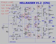
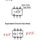
Not bad , just flipped around. But it's still an error.Another thing is I think there is a silkscreen error on q4 and q5. Pin 1 of HN1B01F should be rotates. See picture below.
39R/1K (28.5X) determines the global gain of the amp , 33R/820R would be 26X.
R6/R8/R9 determine how hard the servo works to zero the offset. My sim uses 6.8K for all. Red LED Vf is more sensitive to voltage changes
at <1.5mA. This is better , since we are leveraging this to make the CCS's voltage controlled.
Circuit should work even with even far different values , these discrepancies just "tweak" it for perfection.
If these are built .... the SMD toshiba's might need "tweaking" ,as I use BCxxx for models...
OS
I made several IPS from slewmaster thread, symasui, symetri, eyesee. Testing symasui now, CCS and VAS current are adjusted to spec.

So far only one messsage about an non sucessfully build of the Hellraiser🙁.
In the Spookyamp_V2.1_SMD_package the schematic and pcb do not match. For instance C6 is connected to R7 and R6 in the PCB, the schematic shows a
connection to R4/R5 and R31. Does anybody know, whats wrong here?


In the Spookyamp_V2.1_SMD_package the schematic and pcb do not match. For instance C6 is connected to R7 and R6 in the PCB, the schematic shows a
connection to R4/R5 and R31. Does anybody know, whats wrong here?
I hope that the author of this work, @ostripper can chime in to make some clearness about this topic.
Gaetano.
Gaetano.
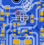
@chat72 i,m looking at building the Infidel but cannot find which smd transistors are used on it, could you help me out here?Here is my build, OPS is mini ef3 version 1.1. Schematic value except re=0E33 and output vbe is ksc2690. There is one issue with this board, you must cross between j1 and j2 see picture below.
IPS is infidel v1.0 all value follow schematic with one issue on silkscreen, at r21 use 22k and at r22 use 820E, see picture below.
Offset is rock-solid stay at almost 0mv. I have a bit of problem with mje340 as an output vbe, bias jump up sometime, change to ksc2690 solved that.
VAS current is set by dial r14. I have v=1.2v across r14//r15. I set r14 so that r14//r15 is around 320E.
SMD trimmer is expensive compare to chinese made trimmer, it’s on ips so you can easily change it later.
View attachment 1269820
View attachment 1269821
Thanks
Its unfortunate there are no proper schematics just LTSpice screen captures, If you download the Infidel_V1.0-package.zip from post #1, there's a schematic jpg, change the transistor types to their smd equivalents:
BC550 to BC850C
BC560 to BC860C
KSA992 to FJV992F
KSC1845 to FJV1845F
Q10 - 2SA1419
Q11 - 2SC3649
Also read this post - https://www.diyaudio.com/community/...-wolverine-compatible-ips.398785/post-7470392
BC550 to BC850C
BC560 to BC860C
KSA992 to FJV992F
KSC1845 to FJV1845F
Q10 - 2SA1419
Q11 - 2SC3649
Also read this post - https://www.diyaudio.com/community/...-wolverine-compatible-ips.398785/post-7470392
That's great thanks and good advice for most of the transistors on the board it has three places for dual Ic's I take it I will be OK to take cues from the Spooky bom to populate these?Its unfortunate there are no proper schematics just LTSpice screen captures, If you download the Infidel_V1.0-package.zip from post #1, there's a schematic jpg, change the transistor types to their smd equivalents:
BC550 to BC850C
BC560 to BC860C
KSA992 to FJV992F
KSC1845 to FJV1845F
Q10 - 2SA1419
Q11 - 2SC3649
Also read this post - https://www.diyaudio.com/community/...-wolverine-compatible-ips.398785/post-7470392
- Home
- Amplifiers
- Solid State
- Spooky and Hellraiser SMD 60W amps (Wolverine compatible IPS)