So I guess it would be good to keep the port expander. Both soft-start and multiple temp sensors make use of it.I used TC74xAT (replace the x with 0-7) TO220 temp sensors. Just bolt them to whatever you want to monitor the temperature of. I did a tiny board for them that had an I2C plug and a cap on it that sandwiched the transistor down. On our big amp boards we put it right on the amp board.
I saw the TC74A0-5.0VAT , does the I2C "poll it" ? And what determines the trigger point , is there a line in code for Celsius ?
Center tab is ground , does it have to be isolated ?
How about the buffer for the port expander , if I used a opto-BJT combo for the relays .... would I need it ?
I am standardizing any sensor opto to the 6N135 ($0.75) , SS mosfet drivers will be your ASSR-V622 (2.50) ... I like the fancy "turn-off" circuit.
I am keeping any of these SMD projects "doable" with the largest packages available (SOT / DIP8)
OS
The temp sensors just run on the I2C bus so the port expander doesn't make any difference for them. You read the temperature from the sender in Celsius, then you compare it to a set point you select for the alarm temperature. The reading rolls over below 0C so it should be constrained to stop strange stuff from happening in the cold.
const int tempLimit = 80; // shut down temperature in Celsius
Wire.beginTransmission(temp1Address); // select the sensor's address
Wire.write(0); // Sends a bit asking for register 0, the data register of the TC74 sensor
Wire.endTransmission(); // this ends transmission of data from the arduino to the temperature sensor
Wire.requestFrom (temp1Address, 1); // ask for 1 byte from the sensor
while (Wire.available()) // slave may send less than requested
temperature1 = Wire.read(); // receive a byte
if (temperature1 < 191) { // constrain the temperature readings to above 0C
if (temperature1 > tempLimit) { // if above the limit
Stop_on_Overheat(); //shut the amp down
MCP23008 can source or sink 20mA per IO pin. That could easily direct drive a transistor or opto.
Yeah , this going to be a lot of boards ...ok, thanks i guess i can hold off a little longer.the reason being is id like to place a single order for PCBs and BOM componets together including for the protection circuits.
My system will be a DIYA dissipante 400mm case with -
- ( 2 PCB's) 1 "Arcwelder beast" (for the sub).
- (4 PCB's) "mini's , for my 100w satellites ..... 2.1 amp.
- (1 PCB) main - digital - protection board.
- 3 output relay boards , 1 soft start , 2 Arcwelder PS PCB's.
A standard stereo single supply setup would need 9 boards.
The reason I'm designing ALL the boards is complete "mix and match" compatibility.
OS

I was just wondering whether the I2C bus could handle the multitasking of thermal/soft-start ?The temp sensors just run on the I2C bus so the port expander doesn't make any difference for them. You read the temperature from the sender in Celsius, then you compare it to a set point you select for the alarm temperature. The reading rolls over below 0C so it should be constrained to stop strange stuff from happening in the cold.
Also , with the I2C bus connected to a small OLED .... could we read states or error codes as text (on the display) - that would be neato !!
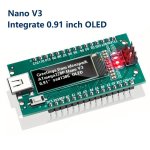
For 10$ , they even have a NANO with a oled (below)- besides having to install the display's library , the display uses minimum resources.
I would add a connector (I2C) and use a better display.
OS
Attachments
I2C displays really slow the loop down. It takes a while to write to a display over I2C. A display should have it's own microcontroller. That's why I did the error reporting code thing to communicate between two microcontrollers. The protection controller writes binary codes to a small port expander. The display microcontroller reads the port expander and displays the messages on the screen.
As for controlling the softstart, ect, no problem. The only issue with remote connection to MCP23008 is if you lose connection you need to reboot the microcontroller to re-establish communication, but I've done it many times myself with no issue. Dumb expanders like PCF8574 don't have this issue.
As for controlling the softstart, ect, no problem. The only issue with remote connection to MCP23008 is if you lose connection you need to reboot the microcontroller to re-establish communication, but I've done it many times myself with no issue. Dumb expanders like PCF8574 don't have this issue.
Most do , small ones use https://www.orientdisplay.com/pdf/AC780S.pdf something like that .... 3 blocks of internal RAM , the display reads fromI2C displays really slow the loop down. It takes a while to write to a display over I2C. A display should have it's own microcontroller.
the controllers RAM , not the Nano's. Just simple text.
I was not talking about a scanned full color TFT. those need some "grunt" (ESPxxx).
Edit - I definitely want the dumb expander.
OS
Getting all ready for some real Hi-fi on the SOURCE end -
94% life 1TB Samsung NVME's are just 28$ these days. Bought two , one for FLAC and one for MP3.
So crazy to see the mechanical HHD go for 5 seconds , and then just a burst on the NVME for <.5 sec.
"Need for speed" is justified with 82K songs to search....
OS
94% life 1TB Samsung NVME's are just 28$ these days. Bought two , one for FLAC and one for MP3.
So crazy to see the mechanical HHD go for 5 seconds , and then just a burst on the NVME for <.5 sec.
"Need for speed" is justified with 82K songs to search....
OS
Attachments

WOW ! The 82K library took 2 min. to build vs. 20 minutes on a mechanical.
Search is nearly instant on the NVME.
OS
Search is nearly instant on the NVME.
OS
The "Beast" OPS is complete and posted (with updated BOM). "Mini" also has the BOM updated. I actually forgot the diodes !! (Vbe Q103/4 is also included).
Beast has different emitter resistors - https://www.mouser.com/ProductDetai...onics/WP4S-R22JA1?qs=cdbOS8ANM9DrnMJBDhLIKQ==
Reasonable priced flameproof variety.
I already have the "blameless" (Infidel) and Symasui designed , they just need BOM's.
Then , I can have fun with the protection . Output relay and soft-start boards should be easy.
Finally , the Nano based main control board. I'll keep everything standardized and as simple as possible.
OS
(moved discussion from wolverine thread OS) Looks like I'm going to have to teach myself SMD soldering, and give this a try next winter. Hopefully I can make it work with 85V rails 😈Yeah , I don't want to go back later to find I should of done something differently. Like the "Beast" EF3 (below) , added base-stoppers for the bigger
drivers , and definitely added the opto for protection.
So , the "Ducks" are in line to integrate anything with anything else.
To get the "ecosystem" standardized will make future additions easy.
OS
You can use the through-hole wolverine IPS with this output stage. It's just a bigger version of what stuart sells.(moved discussion from wolverine thread OS) Looks like I'm going to have to teach myself SMD soldering, and give this a try next winter. Hopefully I can make it work with 85V rails
I would of made it all through-hole (ops) , but the protection circuitry is convenient on the bottom.
Easy , Opto is a smd DIP-8 (big!)
When I build these for myself , I will make a jig to test pre-made IPS's (sell them with tests).
SMD (my way) uses the largest form factors . SOT-23-6 , 2010 resistors , large SMD VAS trannies. No small sot-363.
Low wattage resistors are the small things (0805).
I designed this stuff to be the "bridge" between TH and SMD world.
OS
Oh yeah , FZT857 and 957 are the 300V'ers. A little higher Cob - https://www.mouser.com/datasheet/2/115/DIOD_S_A0002833707_1-2541998.pdf
Arcwelder beast is good to go for even a full 85-90V supply.
At that obscene level this OPS could pass 11A AC out to a speaker , which would be 1.5KW. Since it does not use MT-200's ...
that would be a peak (or 2 ). Still , you would have quite the headroom.
The best outputs would be 15A (ON3281/1302) , "better" more aggressive SOA @ 80V. Drivers on this creation are outputs -
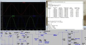
Sanken 3263/1294 is quite different than most outputs (60Mhz Ft and 250p Cob) It's just a big driver.
I think I did use these (as drivers) when I had my "slewmaster". THD is 40ppm .... oh, well - this will be my sub amp.
OS
Arcwelder beast is good to go for even a full 85-90V supply.
At that obscene level this OPS could pass 11A AC out to a speaker , which would be 1.5KW. Since it does not use MT-200's ...
that would be a peak (or 2 ). Still , you would have quite the headroom.
The best outputs would be 15A (ON3281/1302) , "better" more aggressive SOA @ 80V. Drivers on this creation are outputs -
Sanken 3263/1294 is quite different than most outputs (60Mhz Ft and 250p Cob) It's just a big driver.
I think I did use these (as drivers) when I had my "slewmaster". THD is 40ppm .... oh, well - this will be my sub amp.
OS
Attachments
Last edited:
Sorry , must of not dropped the .XLS into the zip file. I corrected the beast BOM along with the mini , as they are nearly identical except
for the extra outputs.
I was thinking , the mini suggested outputs should be them Sanken 2SC3263/2SA1294 devices. They seem to be stocked widely everywhere
(except mouser).
The "weaker" of the pair (2SA1294) states 35Mhz Ft , this rises to 50+ if you get the "Y" grade. Y typically has 100+ current gain. My
HK680 (grandfather amp) uses 2SC4793/2SA1873 driver , 2SC3263/2SA1294 output X2. Drivers have no heatsink ,with the 2'nd Vbe sandwiched
between. These even stay cool with typical use.
OS
Found another pair in this world of non-linear devices. Toshiba also makes the TTC011/TTA006 pair. 230V TO-126.
Of course , Mouser only has the N channel , with P backordered 9/23.
No more 2sa1381's , either (obsolete). Perhaps I should integrate SMD for the pre-drivers and cap multipliers.
But , even here we just have FZT857/957 , 2SA1419/2SC3649. Mouser has all 4 of those at 1$ each.
"Pickings" are getting lean for audio.....
PS - If it was not for the Japanese , we would be "up the creek" .
OS
Anything wrong with KSA1381/KSC3503?No more 2sa1381's , either (obsolete).
They are 2SC4793/2SA1837, repacked to TO-126.Toshiba also makes the TTC011/TTA006 pair. 230V TO-126.
- Home
- Amplifiers
- Solid State
- Spooky and Hellraiser SMD 60W amps (Wolverine compatible IPS)