There are a lot more ways to assemble SMT than through hole. I find it a lot faster to assemble and also easier to rework.

Neat , even as I offer this (and insist) - as FULLY open source. I might make pre-tested IPS's (and sell them).
Not to make a lot of money , but to get the quality out to the "golden ears" and buy some needed test equiptment.
I only have a software scope, a chinese semi tester and a DVM now. I want a better scope !
2 soldering irons , lots of solder from the slewmaster days ! solder sucker and wick.
I've been here on the solid state forum since 2008 , did not know squat ! Different times.
JW , any ideas and suggestions on a combo protection and soft start project to complete this "ecosystem" ?
I have several layouts starting with the "21'st century" and others that are being used on wolverines.
We don't have to get too fancy , the Mini most likely won't need soft start. My amp will be 3-4 amps in single
box (2 X250VA) trafo's .... might need a soft start.
A question about mouser BOM's .... can I just make my own ? They say you can ? just standard XLS in the mouser order format.
This will save me any redundancy. I can make a XLS BOM and have any description/ build guide separate and included in the
project "packages".
This should be easy since I'm using the same parts globally for all my IPS's.
OS
Last edited:
I might make pre-tested IPS's (and sell them).
Not to make a lot of money
ha! spending so much time on this project --> you SHOULD make (at least) some money out of this !
make a GB with SMD presoldered via factory (to save your time). a lot of people will be interested 🙂
I looked at the Symasui 2.0 simulation and here are my thoughts.
I looked at it and nothing pops out as problematic, but there is one big caveat.
Using TTC/A as both the VAS and predrivers gives you some built in harmonic cancellation. As the Vce of Q106 increases, the Vce of Q12 decreases. Since the early effect of both load the VAS equally (hidden feature of this topology), their 2nd harmonics will cancel. I saw a total cancellation null in the simulation of about 17db. This is serendipitous, but it also means that the distortion could vary considerably between builds depending on manufacturing variations. The deeper the null, the larger the variation you can expect. That null is filled in by other distortions to some extent, but I suspect this may show up at or berlow 1KHz. In simulation the transistors are perfectly matched, so the simulation results may be misleading here. A possible surprise for the prototype...
The difference in Ic between the VAS and predrivers will also affect the null since early effect loading is proportional to Ic, so to hit the middle of the statistical distribution you would want to run the VAS and predriver Ic at the same current.
To reduce the early effect distortions altogether you could see about reducing the VAS and predriver Ic to half, so the variation in null will still be there but the overal contribution of harmonics from early effect loading would also be halved. As well as slew rate, and we don't want the predrivers going into class AB. So juggling distortion mechanisms...
I can put together a protection system for it. I'll see what parts are still available when I get a chance.
Kicad is free and is probably the go to these days. I have yet to try it out.
As for my statements on verifying your designs. These are new pcb layouts, maybe not new designs but they still need both mechanical and electrical verification, testing to see if they meet the required specifications. You can mess up a well simulated design with a layout and real components.
On the Mouser BOM ? I understand that you can use a xls file to upload to the project manager. I do not do it that way since I have my own methods. But it only accepts mouser or mfr pn and quantity. It comes down to your process for loading the info into Mouser, what your ecad is capable of or if you do it manually. I use the available tools to do the monkey work of typing lines of entries, it can all be done manually, it just takes more time to create and check for accuracy.
LTspice can generate a bom? Might be an option for you since your schematics are used as the reference. Still might require massaging the data into a uploadable format=monkey work
Last edited:
Here's what the stencils look like. You just spread solder paste across it with something with an edge like a credit card. The thickness of the stencil controls the amount of paste being placed on the board. After the solder is spread, remove the stencil, drop the parts on and bake.
Attachments
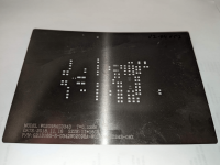
One usually uses tooling or other mechanical holes for alignment of a stencil. So those holes need to be present in the Gerber data for them to be part of the stencil.
I have a number of protection and soft-start ckts designed, name your requirements? Some are designed for a Dissipante chassis usage.
I have a number of protection and soft-start ckts designed, name your requirements? Some are designed for a Dissipante chassis usage.
Last edited:
How do you make those stencils?Here's what the stencils look like. You just spread solder paste across it with something with an edge like a credit card. The thickness of the stencil controls the amount of paste being placed on the board. After the solder is spread, remove the stencil, drop the parts on and bake.

Btw, I got myself one of those “baking” tables and assembling SMDs just so much faster compared to soldering THT parts.
I was looking at that same heating table! That would simplify my process. Does the temperature stay consistent?
Does the temperature stay consistent?
Once you flip the on switch, it starts heat up slowly for about three minutes. You can also set the temperature where you want it to stop.
Manual in Chinese though, I'm still learning the thing... by pressing all of the buttons and observing what it does as a result... 🤣🙂
I wonder if JLC pcb has something like that. Probably should.My board house laser cuts the stencils when I order boards.
I tried applying the paste solder with small flat head screwdriver, but it is just too messy.
Yes, JLCPCB has the option to make a stencil when you're ordering the pcb.
This JBC paste dispenser with 22Ga tips works great, it eliminated the hand cramp I'd get from pressing the solder paste plunger with my thumb😉.
Syringes
https://a.co/d/hkterXZ
This JBC paste dispenser with 22Ga tips works great, it eliminated the hand cramp I'd get from pressing the solder paste plunger with my thumb😉.
Syringes
https://a.co/d/hkterXZ
I'll have to read more on this "baking" technique.
OS
1. Adjustable or software defined overcurrent. (leveraged by the output Re's)
2. Temperature
3. DC
4. Extra "trip point" - software defined.
5. Time based reset and fault triggering.
6. Verbose led outputs indicating which fault occurred.
7. Cheap (china nano) based. 5V - nano has the 3.3V reg. built in.
Might be better to leave the soft start separate - some smaller units could just be MOV ,
larger use big resistors and timed relay - simple.
Power board that goes with the mini has 24V outputs - protection would just need 12V/5V regs.
OS
OS
Hmmm ... stereo (2 channel)One usually uses tooling or other mechanical holes for alignment of a stencil. So those holes need to be present in the Gerber data for them to be part of the stencil.
I have a number of protection and soft-start ckts designed, name your requirements? Some are designed for a Dissipante chassis usage.
1. Adjustable or software defined overcurrent. (leveraged by the output Re's)
2. Temperature
3. DC
4. Extra "trip point" - software defined.
5. Time based reset and fault triggering.
6. Verbose led outputs indicating which fault occurred.
7. Cheap (china nano) based. 5V - nano has the 3.3V reg. built in.
Might be better to leave the soft start separate - some smaller units could just be MOV ,
larger use big resistors and timed relay - simple.
Power board that goes with the mini has 24V outputs - protection would just need 12V/5V regs.
OS
Last of the IPS's - for now , Symasui (below).
By really speccing out the SMD pads , I now know exactly what packages I will use for all 4.
BOM.zip will have the Mouser XLS's for every one I finish. I will update it until it has all 7 boards in it.
OS
By really speccing out the SMD pads , I now know exactly what packages I will use for all 4.
BOM.zip will have the Mouser XLS's for every one I finish. I will update it until it has all 7 boards in it.
OS
Attachments

You want to use a mcu(7), I don’t have such a design. Imo over kill, not a good solution for diy unless you are supplying the programmed mcu. Expecting folks to buy a mcu (nano), programmer, mechanical aspects, figuring that all out may be too much for them. Not lean and mean, extra expense, space, little bang for the $, eligant yes but at a cost. Good if you need features liked controlled power on etc.
If so, Valery was kind enough to post his sketch (code) for Arduino for you to use as a starting point, good luck with coding, more stuff to learn and support.
If folks need a softstart, Ac inlet, fusing, filtering, for the Dissipante chassis I can offer them that design.
If so, Valery was kind enough to post his sketch (code) for Arduino for you to use as a starting point, good luck with coding, more stuff to learn and support.
If folks need a softstart, Ac inlet, fusing, filtering, for the Dissipante chassis I can offer them that design.
Last edited:
You mentioned Dissipante specifically. It is a minor consideration, but if boards intended to be mounted on heatsinks wind up being UMS compatible, that is wonderful. For boards generally intended to be mounted on the base of the chassis, conforming with the standard grid of the ModuShop base plates is a nice feature.
I can't (and won't) speak for others, but while some say drilling and tapping is "easy", it is a put off for me. I'm quite capable of doing it, but I don't like it. I see that optimizing PCB area is a key design criteria, so chances are limited, but I thought I'd mention it.
Those that can (and like to) drill and tap likely don't care about the spacing... those that can't (or don't like to) will likely greatly appreciate the small consideration.
Looking forward to trying these out.
A Nano board just needs a USB cable for programming, everything is on board already. Simply dumping Arduino code onto them is really easy if given step by step instruction. Adjusting critical time functions is much easier in code than calculating corner frequencies, ect if the code is structured properly.Expecting folks to buy a mcu (nano), programmer, mechanical aspects, figuring that all out may be too much for them.
- Home
- Amplifiers
- Solid State
- Spooky and Hellraiser SMD 60W amps (Wolverine compatible IPS)