Hello Everybody,
So I require some help to solve a quite straightforward task, that is modifying a class A SE amplifier so it will use a single power supply instead of a split one.
The amp to be modded is

available from: https://sound-au.com/project10.htm
The idea is to change the +/- 20V to a single +40v, of course adding an output cap...
I have not been able to succeed in such a task.
Your help is welcome 🙂
Please do not make suggestions for :
-keep using it with a dual supply
-change this or that to make it a boring amp (most often called "blameless")
I also attach the LTspice file as I believe it will be useful 🙂
This was a personal exercise that I was not able to do on my own, thanks for your help!
cheers from Switzerland
So I require some help to solve a quite straightforward task, that is modifying a class A SE amplifier so it will use a single power supply instead of a split one.
The amp to be modded is
available from: https://sound-au.com/project10.htm
The idea is to change the +/- 20V to a single +40v, of course adding an output cap...
I have not been able to succeed in such a task.
Your help is welcome 🙂
Please do not make suggestions for :
-keep using it with a dual supply
-change this or that to make it a boring amp (most often called "blameless")
I also attach the LTspice file as I believe it will be useful 🙂
This was a personal exercise that I was not able to do on my own, thanks for your help!
cheers from Switzerland
Attachments
Here is a good article about running op-amps off a single supply. If you think of your amplifier as a scaled-up version of an op-amp, the same principles apply here.
https://www.analog.com/en/analog-dialogue/articles/avoiding-op-amp-instability-problems.html
In short, you can accomplish this by:
https://www.analog.com/en/analog-dialogue/articles/avoiding-op-amp-instability-problems.html
In short, you can accomplish this by:
- Bias the base of Q1 at around half the supply voltage. The simplest way to do this is double the value of R1, and then connect another resistor of equal value from the junction of C1-R1-R2 to the positive supply.
- Connect the negative rail to ground.
- Add an output capacitor (positive towards the output transistors)

I NEVER said that there was anything wrong, before answering and sharing your feelings, read the question.What´s wrong with Rodd Elliott´s design is way beyond me.
I find no good purpose in your idea.
Last edited:
Well, I'm not a fan of class-A, especially single ended, but the same ideas apply to single PS. See attached:
A Push-pull class-A gives the same output with half the dissipation.
A Push-pull class-A gives the same output with half the dissipation.
Attachments

Last edited:
Thanks man, I was missing biasing the base of Q1 at 1/2 V+Here is a good article about running op-amps off a single supply. If you think of your amplifier as a scaled-up version of an op-amp, the same principles apply here.
https://www.analog.com/en/analog-dialogue/articles/avoiding-op-amp-instability-problems.html
In short, you can accomplish this by:
- Bias the base of Q1 at around half the supply voltage. The simplest way to do this is double the value of R1, and then connect another resistor of equal value from the junction of C1-R1-R2 to the positive supply.
- Connect the negative rail to ground.
- Add an output capacitor (positive towards the output transistors)
Thanks for the attachment and interesting ideas.Well, I'm not a fan of class-A, especially single ended, but the same ideas apply to single PS. See attached:
And double the R7 value connecting it to positive rail, to mantain the same output current.
I am not getting it... here I attach the schematic so perhaps you may give me additional clues...And double the R7 value connecting it to positive rail, to mantain the same output current.
Attachments
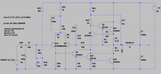
Thank you very much 😀Here is a single 40V supply class-A push-pull amplifier.
Take R72 close to 4.7K.
Done, thanks, I will check if other things are to be changed, Gracias por su ayuda 🙂
I did read the question and answered what I think about it.I NEVER said that there was anything wrong, before answering and sharing your feelings, read the question.
EVERYTHING that is posted on a Public Forum is open/asking for answers, EVERYTHING.
(emphasis on exchanged and debate)Dictionary Definitions from Oxford Languages · Learn more
/ˈfɔːrəm/ noun: forum; plural noun: forums; plural noun: fora
1.
a meeting or medium where ideas and views on a particular issue can be exchanged.
"we hope these pages act as a forum for debate"
Not such a good idea biassing Q1 that way - R1 will inject supply ripple straight into the signal path.
Better make a divider with a pair of 2k2 resistors, bypass the lower leg with some capacitance (how much depends on whether you're getting rid of 100Hz from a linear supply or HF from a SMPS) and take the original R1 (22k) to the junction.
I'm doing something similar with a JLH, making it single rail so I can use a 48V SMPS that I just happen to have lying around.
You may wish to try the DoZ, very similar sound and schematic to the JLH, except it reject hum from power supply much better and also it is single rail 😉Not such a good idea biassing Q1 that way - R1 will inject supply ripple straight into the signal path.
Better make a divider with a pair of 2k2 resistors, bypass the lower leg with some capacitance (how much depends on whether you're getting rid of 100Hz from a linear supply or HF from a SMPS) and take the original R1 (22k) to the junction.
I'm doing something similar with a JLH, making it single rail so I can use a 48V SMPS that I just happen to have lying around.
If you can make a quick n dirty drawing it would be easier to me thanks manNot such a good idea biassing Q1 that way - R1 will inject supply ripple straight into the signal path.
Better make a divider with a pair of 2k2 resistors, bypass the lower leg with some capacitance (how much depends on whether you're getting rid of 100Hz from a linear supply or HF from a SMPS) and take the original R1 (22k) to the junction.
I'm doing something similar with a JLH, making it single rail so I can use a 48V SMPS that I just happen to have lying around.
I can attach an LTspice schematic at some point but for now, how about (referring to your original schematic):If you can make a quick n dirty drawing it would be easier to me thanks man
2k2 resistor: one end to +20V, other end to lower end of R1. Let's call this new node "Vcc/2"
Another 2k2 resistor: one end to Vcc/2, other end to -20V
A capacitor, probably 100uF 35V, in parallel with the second 2k2.
R72 as described by Osvaldo
-v pin of C3 to -20V or Vcc/2, I haven't modelled the latter.
Regarding DOZ, yes I may well end up using that, but for now I'm looking at the updated JLH with two pairs of output transistors:
https://sound-au.com/tcaas/jlhupdate.htm
I design all my stuff with SE power because it's a lot easier to make (and I mostly use tubes so no PNP garbage)... Maybe that's the point here, too. Never mind the fact the PSU costs less since there's only one rail to filter. OTOH, you add cost with the output cap...What´s wrong with Rodd Elliott´s design is way beyond me.
I find no good purpose in your idea.
- Home
- Amplifiers
- Solid State
- Split Supply to Single Supply for Class A SE -simple amp-