No need for DC-sensing loudspeaker protection, either (if you arrange the output to come up gracefully). Sure, amps don't often go DC but my speakers are worth a hell of a lot more than any of my amps.I design all my stuff with SE power because it's a lot easier to make (and I mostly use tubes so no PNP garbage)... Maybe that's the point here, too. Never mind the fact the PSU costs less since there's only one rail to filter. OTOH, you add cost with the output cap...

That's why I actually prefer transformer coupled output 🙂
That and I've only built one solid state amp LOL - That one uses a 10,000µF/100V cap for speaker coupling.
That and I've only built one solid state amp LOL - That one uses a 10,000µF/100V cap for speaker coupling.
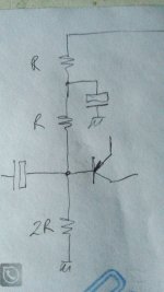
Here is my last version:I can attach an LTspice schematic at some point but for now, how about (referring to your original schematic):
2k2 resistor: one end to +20V, other end to lower end of R1. Let's call this new node "Vcc/2"
Another 2k2 resistor: one end to Vcc/2, other end to -20V
A capacitor, probably 100uF 35V, in parallel with the second 2k2.
R72 as described by Osvaldo
-v pin of C3 to -20V or Vcc/2, I haven't modelled the latter.
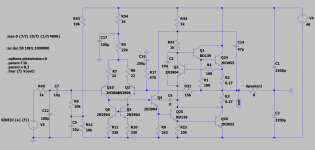
Regarding DOZ, yes I may well end up using that, but for now I'm looking at the updated JLH with two pairs of output transistors:
https://sound-au.com/tcaas/jlhupdate.htm
Attachments
Sure, but it's not as important as the current mirror. Either way, the IPS needs one or both to remove supply voltage dependencies.What about changing R5 by a CCS?
Now that I have the single supply class A ( Thanks Osvaldo de Banfield, Rory Christ,Steveu, bremen nacht), I will make some adjustments , to test adaptive bias (AKA sliding bias). 🙂
If there is a chance for the speaker to be disconnected, rememer put a large resistor (1K suffices) to mantain the output cap charged and prevent pops when reconecting.
- Home
- Amplifiers
- Solid State
- Split Supply to Single Supply for Class A SE -simple amp-