Klewis, find a diagram of the wiring system of a house and you will have an idea of where the ground goes. I don't know why you would get no current through that resistor, unless your voltage source had too high a frequency or too low a voltage. Or you had accidentally given one of your caps a low value parallel resistance instead of series resistance.
For the inductors you need to have a coupling parameter, for instance
K1 L1 L2 .9
Where .9 is the coupling coefficient; 1 is perfect but not realistic. You will need to flip the inductors depending on whether the coupling is common-mode or differential-mode. I think the chokes in line filters are common-mode (not sure).
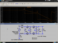
Here's a schematic for my Feller filter, with improvised house wiring (bad guess probably). Response graph is probably unrealistic too.
- keantoken
For the inductors you need to have a coupling parameter, for instance
K1 L1 L2 .9
Where .9 is the coupling coefficient; 1 is perfect but not realistic. You will need to flip the inductors depending on whether the coupling is common-mode or differential-mode. I think the chokes in line filters are common-mode (not sure).
Here's a schematic for my Feller filter, with improvised house wiring (bad guess probably). Response graph is probably unrealistic too.
- keantoken
Attachments
keantoken is correct, the sine source needs to be ground referenced. for 6 amps, make R3 20 ohms. if you need to simulate noise on the line, you can add a noise source in series with the sine source (for the frequency response test make the AC parameter of the noise source 0V). all voltage sources in LTSpice are zero output resistance by default.
i think the resistance between neutral and ground is more realistically around 100-200 milliohms. there's quite a bit of footage of copper in those walls, and a lot of the integrity of the ground and neutral runs depends on the skill of whoever installed the wiring. i once tried to help somebody figure out a wiring problem in their house, and the neutral and ground at the end of a string of outlets had about 1 ohm between them (with a 10 amp load, the difference between neutral and ground was 10V, and 110V between neutral and hot). now that's extreme (and dangerous) (fortunately, tightening up some screws on some of the outlets in the string brought it down to about 0.2 ohms). likewise, poorly installed grounds can be a hazard if something shorts to ground.
i think the resistance between neutral and ground is more realistically around 100-200 milliohms. there's quite a bit of footage of copper in those walls, and a lot of the integrity of the ground and neutral runs depends on the skill of whoever installed the wiring. i once tried to help somebody figure out a wiring problem in their house, and the neutral and ground at the end of a string of outlets had about 1 ohm between them (with a 10 amp load, the difference between neutral and ground was 10V, and 110V between neutral and hot). now that's extreme (and dangerous) (fortunately, tightening up some screws on some of the outlets in the string brought it down to about 0.2 ohms). likewise, poorly installed grounds can be a hazard if something shorts to ground.
That's interesting, maybe I should take apart all my sockets and tighten (solder?) them. But tell me what's the solution when none of your outlets are grounded? We have a grounding post outside but that seems to be a luxury exclusively for the phone box and electric meter.
- keantoken
- keantoken
That's interesting, maybe I should take apart all my sockets and tighten (solder?) them. But tell me what's the solution when none of your outlets are grounded? We have a grounding post outside but that seems to be a luxury exclusively for the phone box and electric meter.
- keantoken
Thanks for the help. Kean, no don't solder your outlets. The reason the screws seem to loosen is because when you draw significant current through an outlet, the wire heats up and expands. With the expansion, either the screw stretches, or the wire compresses. Either of these actions are permanent, so, the screw to wire contact is reduced. This bad contact then increases the heat when current is drawn and the process repeats until the contact is pretty weak and the screw is quite loose. In modern house wiring the neutral and ground are joined at the fuse/circuit breaker panel. It's a safety thing, two ground paths are better than one and also better in case their is current on the neutral in the particular circuit. In older houses, the neutral is also the ground and is connected to the earth ground at the panel.
Ken
soldering is a bad idea, because if the solder melts and oozes down inside the outlet, it can cause a fire. you don't want anything in house wiring that can melt and migrate.
I use SPICE to good effect, but I don't rely on it to give very
accurate results for non-linear circuits. I have to smile if someone
quotes parts-per-million distortion figures from a simulation.
True!
True!
Mike,
I don't disagree with what Nelson said in the quote, but that is far, far from supporting your overly-general statements that SPICE is of no use in THD simulations. The truth is that when you get into parts per million (i.e., below 0.001%) there are MANY real world things that are not modeled in a typical SPICE simulation, like magnetic coupling and other physical design related things.
But for an amplifier that is well implemented, SPICE distortion simulations are very useful down to better than 0.01%.
You are throwing the baby out with the bathwater when you make your very general claims like this, as you have on several other threads.
Buy my book, read the two chapters on SPICE, use my models and then see what you get. If you go to my website, you can be up and running with LTspice in about 10 minutes, with good models freely available to boot.
Cheers,
Bob
Mike,
[snip]
The truth is that when you get into parts per million (i.e., below 0.001%) there are MANY real world things that are not modeled in a typical SPICE simulation, like magnetic coupling and other physical design related things.
[snip]
Cheers,
Bob
Hi Bob,
As for magnetic coupling, it's quite easy to simulate the effects. Just insert small inductors into the traces/leads who are involved and define the coupling coefficients. Admittedly, it's a bit of guesswork if you don't have specialized software. In that case one have to revert to simple rules of thumb, but it can be done (or use my magic little pot to cancel it out 🙂).
Cheers,
E.
Edmund, this is a very poor answer.
As a rough rule of thumb, the inductance of a pc trace will be 100 nH/inch. Maybe, Howard Johnson, has some equations to cover this and also the mutual inductance. See: Signal Consulting, Inc. - Dr. Howard Johnson
As a rough rule of thumb, the inductance of a pc trace will be 100 nH/inch. Maybe, Howard Johnson, has some equations to cover this and also the mutual inductance. See: Signal Consulting, Inc. - Dr. Howard Johnson
rules of thumb
Yes, I know it was a lame and lousy answer. I wasn't in the right mood. Sorry.
Besides, I wanted to avoid a discussion about the accuracy of these rules of thumb, as there are many of them.
BTW, normally I'm called Edmond.
Cheers,
E.
Edmund, this is a very poor answer.
[snip]
Yes, I know it was a lame and lousy answer. I wasn't in the right mood. Sorry.
Besides, I wanted to avoid a discussion about the accuracy of these rules of thumb, as there are many of them.
BTW, normally I'm called Edmond.
Cheers,
E.
Simulation in the Browser
Hey Guys, Not sure if this is the right place to post - but we are considering adding simulation to Upverter.com and I'd love to chat with some of you about what it would need to be able to do to be useful - and how we can avoid re-engineering the wheel.
feel free to email: zak@upverter.com
Thanks!
Zak
Whenever I'm aware that I'm reinventing a wheel I'm haunted by the knowledge that I may inadvertently leave a corner on it someplace - so I make an effort to understand and emulate, as much as possible, the craftsmanship displayed by previous wheelmakers.. . . we are considering adding simulation to Upverter.com . . . what it would need to be able to do to be useful . . . avoid re-engineering the wheel.
Take a good look at the capabilities of LTSpice, a no-charge circuit simulator available from Linear Technology at < Linear Technology - Design Simulation and Device Models >. You should also look at the User's Group, < LTspice : LTspice/SwitcherCAD III >.
Although LTSpice surpasses both the capability and performance of commercial programs costing thousands of dollars per copy, keep in mind that it doesn't claim to be anything more than a circuit simulator. It will not teach you circuit design or network analysis. The schematic diagrams it produces are straightforward and readable, but not up to the standards of many corporate Configuration Management systems. LTSpice will not help you keep track of parts lists, drawing changes, or lay out your printed wiring boards. That may make it an excellent addition to your project, so contact the program's author and architect, Mike Engelhardt , to discuss your specific concept.
The major shortcoming of LTSpice is a lack of comprehensive, well-done, documentation, tutorials, and user support documents - so many third-parties have stepped in to create them. You'll find numerous tutorials and examples in the "Files" and "Links" sections of the User's Group.
Dale
p.s. -
In a forum such as this I much prefer to see discussions conducted as much as possible in the open, public forum rather than taken off-line to private exchanges between individuals. That allows everybody to benefit from - and contribute to - the conversation.. . . feel free to email:
Maybe Candy is lying, but I never trust these measurements performed by such magazines. Besides, as you said, it's difficult to check the performance of a Halcro by means of an AP, for example. They should consult you to get reliable numbers.
Built? No, I'm retired and don't have the facilities any longer to build such amp.But I have designed amp's on paper with a thd (at 20kHz) around 20ppb. If some body give me the money and facilities to build such thing, I should really love it.
Well, it depends on the tools and models, and of course who is doing the simulation, it's really an art, just as building the real thing, to understand the power and limitations of a simulator.
Anyhow, my latest design shows, a thd (20kHz) of 20ppb. Maybe my sim is one order of magnitude wrong, that still leaves a 0.2ppm of distortion.
Cheers, Edmond.
edit: if you are really interested in my design, I'll send you the schematic (confidentially, of course).

0.2ppm 20kHz is hard to achieved with conventional method even in sim.
Is your design similar with halcro's? I got 15ppb 1kHz THD for output stage only. Or did you use EC?
http://www.diyaudio.com/forums/solid-state/6362-halcro-amplifier-6.html#post2823918
Last edited:
0.2ppm 20kHz is hard to achieved with conventional method even in sim.
Is your design similar with halcro's? I got 15ppb 1kHz THD for output stage only. Or did you use EC?
http://www.diyaudio.com/forums/solid-state/6362-halcro-amplifier-6.html#post2823918
Hi Ontoaba,
The schematic is lost or has been deleted and I can't remember all the details. Probably a used a CFB IPS and a CFB OPS, most likely combined with TMC. Anyhow no HEC or Halcro techniques. The IPS and VAS had also cascodes in order to eliminate the Early effect. I do remember that it was a very complex amp (lots of trannies) and I abandoned the concept not only because of that, but also because I realized that in real life 20ppb @ 20kHz (or even 200ppb) is out of reach.
Cheers,
E.
Trying to figure out SIMetrix. Of course the very first circuit I want to look at has some older transistors not in their library. I have a text string Fairchild is nice enough to supply ( 2N5551) The 388 pages of the users manual does not help me know how to get this part into the program. Could anyone offer some suggestions?
- Home
- Design & Build
- Software Tools
- Spice simulation