...and for those who want to do simulation exercises of the loopgain to find the phase and gain margin, here are the LTSpice examples. I know this has been dealt with before but it seems most threads end up hanging.. and for beginners who bites huge chunks and get choked [that was me 😀] .
Sa muli,
Albert

Hello,
How could we made this simulation with balanced amplifier and dual feedback ?
just add one ac gen in only one feedback ?
thanks
...How could we made this simulation with balanced amplifier and dual feedback ?
Easiest way is to transform the balanced signal with a "balun" and then use the standard set up.
I posted an ASC with a balun and dual Tian probes to check the dual feedback loops conveniently.
Just search my posts for that keyword to find it and examples of use
Best wishes
David
Thanks dave
I found two thread with asc :
Feedback, differential? the next advance.
https://www.diyaudio.com/forums/sol...-power-amp-200w8r-400w4r-124.html#post4230613
I found two thread with asc :
Feedback, differential? the next advance.
https://www.diyaudio.com/forums/sol...-power-amp-200w8r-400w4r-124.html#post4230613
...Thanks for this link, but I do not see how to use it in my amp.
can you help me ?
OK, I will post an example when I have some time, maybe a day or two.
Best wishes
David
I had a quick look and the results are not as I expected.
I have never tried to analyse a Circlotron before and there are some issues I don't understand properly.
Do you have links to any examples of a loop gain check of a Circlotron?
Best wishes
David
I have never tried to analyse a Circlotron before and there are some issues I don't understand properly.
Do you have links to any examples of a loop gain check of a Circlotron?
Best wishes
David
hi, I have no example unfortunately, hence my question...
Hi Sébastien
Your circuit is complicated by the double feedback path, and I assumed that was your problem.
So an example of a Circlotron with just one feedback path would have been a simple way to start.
If the problem is how to use a Tian probe in any Circlotron then that's different.
I will have a look and think about it.
Best wishes
David
Hi Dave, thank you for your interest
the simplest is this one :
Build The Amazing FET Circlotron | Pass DIY
the simplest is this one :
Build The Amazing FET Circlotron | Pass DIY
Hi Dave, thank you for your interest
Sorry my DIY mailbox is full but you can Email me directly, the address is in my profile.
Best wishes
David
Not sure if this is the right thread, but I've a tip for simulating mains transformer/rectifier/filter cap PSUs bypassing the initial startup.
I was adding a simple diode/filtercap PSU model to an amp model, and the simulation was taking forever to charge up all the capacitors in the circuit (as there were no DC voltage sources any more, the transient simulation initial conditions did not preset any caps as charged).
So I added DC voltage sources, feeding via 100 ohm resistors to the rails - this set the initial state of the filter caps and other amplifier caps nicely, without distorting the emulation of the whole system under load very much. Now a couple cycles of emulated mains is plenty to establish realistic rail ripple waveforms.
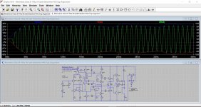
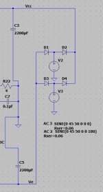
Another I noticed is setting the phase to 90/270 for the AC sources acting as transformer secondaries sets the initial DC state to fully charged capacitors too, ie use a cosine, not a sine.
Interesting.
I haven't really played around with this beyond finding something that gave realistic ripple in simulation. I'm not sure how you can get a DC operating point from just running a transient sim though... maybe I'm not understanding what you have done 🙂
I haven't really played around with this beyond finding something that gave realistic ripple in simulation. I'm not sure how you can get a DC operating point from just running a transient sim though... maybe I'm not understanding what you have done 🙂
Hi Edmond. Please see Winged Areas with your Toshiba 2SK1530EKV 2SJ201EKV models. What's wrong?Hi Andy.
And here is the EKV model for MC8.
As MC8 has some trouble with nonlinear expressions for capacitors, it might be necessary to increase the global parameter RELTOL from 1m to 30m or so, dependent on the time step size in the transient analysis.
Cheers, Edmond.
.SUBCKT 2SK1530EKV 1 2 3
* Node 1 -> Drain
* Node 2 -> Gate
* Node 3 -> Source
***************************************
+PARAMS: Cgdmin = 42.8114p
+PARAMS: Cgdmax = 1216.887p
+PARAMS: a = 0.31548599
+PARAMS: B = { ( Cgdmin + 0.5 * pi * Cgdmax ) / ( 1 + 0.5 * pi ) }
+PARAMS: C = { ( Cgdmax - Cgdmin) / ( 1 + 0.5 * pi ) }
M1 4 5 3 3 NMOS44
RG 2 5 1m
RD 1 4 1m
DDS 3 1 DDS
CGS 5 3 850p
CGD 2 1 { if( V(2,1) > 0, a * tanh( a * V(2,1) ) + B, C * atan( a * V(2,1) ) + B ) }
.MODEL NMOS44 NMOS (LEVEL=44 L=2U W=0.5m
;+ EKVINT = 1
+ cox = 7e-4
+ xj = 1e-8
+ vto=1.97 gamma=5.9999694 phi=3.4298218
+ kp=7.95e-2
+ e0=2.0568449051e+11
+ ucrit=2.6680517254825e+13
+ dl=0 dw=0
+ lambda=1.1305e5
+ ibn=1.0 iba=0 ibb=3.0e8
+ weta=0.0 q0=0 LK=2.9e-7
+ leta=0.0 rsh=0.0
+ )
******************************************
.MODEL DDS D (CJO= 630p VJ=0.9 M=.55
+RS=0.005 IS=1E-10 TT=20.5n N=1.12 BV=200)
*****************************************
.ENDS
Attachments
Last edited:
How to get proper DC points in the stable state?
How do I overcome the initial state DC analysis when I use a 'real transformer' instead of a Voltage Source?
It gives me crazy DC points (like DC=-6mV on a DC 350 V supply) and just to check I added a 10V source across a 100K resistor and the DC point is . . . 1V .
> Normally I use a voltage source say 350V and am happy, but here I have the PS of a Fender and I wanted to know how the ripple goes through the amplifier.

So I thought to use the UIC modifier, but having the Mac version of LTSpice I have no pop-up to help me out; and found nothing on the wikis etc. Using .tran 1m 2.1 2 gives the correct flow of the ripple, but not of the DC!
albert
How do I overcome the initial state DC analysis when I use a 'real transformer' instead of a Voltage Source?
It gives me crazy DC points (like DC=-6mV on a DC 350 V supply) and just to check I added a 10V source across a 100K resistor and the DC point is . . . 1V .
> Normally I use a voltage source say 350V and am happy, but here I have the PS of a Fender and I wanted to know how the ripple goes through the amplifier.
So I thought to use the UIC modifier, but having the Mac version of LTSpice I have no pop-up to help me out; and found nothing on the wikis etc. Using .tran 1m 2.1 2 gives the correct flow of the ripple, but not of the DC!
albert
Last edited:
Who owns NTE2508 (NPN) and NTE2509 (PNP)
Spice simulation, share it. I don't speak english, i use google translate, hope someone can help me, thanks
Spice simulation, share it. I don't speak english, i use google translate, hope someone can help me, thanks
Last edited:
- Home
- Design & Build
- Software Tools
- Spice simulation