Hello,
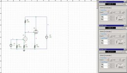
I try to simulate a simple gain stage-> Cathode follower using a 12ax7. Taking some literature/schematics in account it's wise to bias the cathode follower less than 1v ( say 0.5 ) to let flow a small grid current from anode of gain stage. See example schematic.
If I simulate this, the Uk of the cathode follower is not what I assumed. It seemed, that the grid current which should flow if the bias less then 1v is not simulated.
Is this a "normal" issue on spice models, means most/all tube spice models do not simulate this? If I take a look to the model description a grid current simulation is implemented but it seemed to me that this do not work.
At least I would like to get the same behavior of the circuit but with lower HT ( 250v ).
Anny hints?
Attachments
I've seen no reference in the tube specs for grid dissipaton so I think that might be a bad idea.
In addition, dropping the current in the input stage may cut your distortion from 4.7% to 2% (compare 820R vs 1K8) if I am reading this data sheet correctly.
http://www.pentalaboratories.com/pdfs/ECC83.pdf
In addition, dropping the current in the input stage may cut your distortion from 4.7% to 2% (compare 820R vs 1K8) if I am reading this data sheet correctly.
http://www.pentalaboratories.com/pdfs/ECC83.pdf
A quick answer for now, I will look for 12AX7 data and post more later.
It is fairly common for tube SPICE models to ignore grid current. Or if they do model it they just use a diode and a resistor in series with the grid etc. Often there is not any grid current data in a spec sheet, so you have to measure it yourself, this may be a reason why.
In any case, the model you are using does have grid current modeled, but perhaps it is not accurate enough. As written it has grid current starting when grid voltage is -.2 volts or higher. You may want to change this to -1 volts. And you may want to increase the magnitude of the current.
Also it has a grid current that is dependent on grid voltage only, that is not realistic. There is a better grid current model by Rydel, I will look for it and get back later.
but for now try changing the line shown :
from
bgg g k i=5e-6*(uramp(v(g,k)+0.2)^1.5)
to
bgg g k i=2e-5*(uramp(v(g,k)+1.0)^1.5)
These are just guesses on my part, try them and see.
Here is a Rydel style grid current model for the 12AX7.
change from
bgg g k i=5e-6*(uramp(v(g,k)+0.2)^1.5)
to
bgg g k I=IF(V(G,K)>0, 5.10044246234457E-09 * ((( 4238.969348634 +V(A,K))/( 281.39443771702 +V(A,K)))**4)*V(G,K)**1.5,0)
This will gives grid current matching that I have measured in a 12AX7 some time ago.
change from
bgg g k i=5e-6*(uramp(v(g,k)+0.2)^1.5)
to
bgg g k I=IF(V(G,K)>0, 5.10044246234457E-09 * ((( 4238.969348634 +V(A,K))/( 281.39443771702 +V(A,K)))**4)*V(G,K)**1.5,0)
This will gives grid current matching that I have measured in a 12AX7 some time ago.
Last edited:
Here is a Rydel style grid current model for the 12AX7.
change from
bgg g k i=5e-6*(uramp(v(g,k)+0.2)^1.5)
to
bgg g k I=IF(V(G,K)>0, 5.10044246234457E-09 * ((( 4238.969348634 +V(A,K))/( 281.39443771702 +V(A,K)))**4)*V(G,K)**1.5,0)
This will gives grid current matching that I have measured in a 12AX7 some time ago.
Hi Robert,
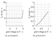
Doesn't the grid start taking current at about -0.6V or so? It looks like the model is set only to start at any G-K Voltage >0V.
I imagine it will mess up the model setting it to -0.6V?
You can get a reasonable model by putting an ideal diode, a 0.5v battery, and a 3k resistor in series, between grid and cathode. Good enough for most applications. Or you can use a non-ideal diode like 1N4148, and a 1V battery and 3k resistor.
Thanks Merlin.
So you agree that current starts to flow at about -0.6V Vg or so?
I have incorporated the Ig model from above into the 12AX7 model I have. It works, but I'm not certain how accurate it is. In the sim with the "standard" CC config, the grid current is peaking at about 50uA with a peak of +0.5V grid voltage.
Here is a graphic jazbo posted on another site.
Attachments
Last edited:
Poynt99 :
Yes, in reality the grid current starts at Vg less than 0. The model I quoted is not accurate in that respect. You are also right that the it would be messed up if you changed it, negative values raised to the power 1.5 will give an error.
I cant think of a good grid current model that works at negative Vg, there may be one, I just cant remember one right now. With some thought the Rydel model could be adapted for negative Vg. I may have done this, I will look later.
I don't like the diode and resistor models, they just give a more or less constant current for any given Vg. Real grid current varies with Vp as well as Vg, the lower Vp, the higher the grid current. The Rydel model handles that aspect, the diode models don't.
I find the Rydel current model to be a good one, just not at negative Vg.
Also bear in mind that it is fit to the particular tube I took the data from, so it will not necessarily match data sheets or graphs you find elsewhere. If you did want a model that that matched a particular tube you need to measure the data or extract the data from the graph and fit the model to that data, ie get the parameters.
Robert
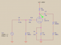
Here is the circuit and scope shot (simulation) of the 12AX7 model incorporating your Ig model.
I'm wondering if there is perhaps a relationship between the tube's mu, Plate curves, and Ig? If so perhaps a more generalized Ig model could be constructed that could be used without having to measure, and could be applied to all tubes?
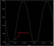
Does the scope shot appear right? Should there be limiting with this circuit and an input level of 2Vp?
I'm wondering if there is perhaps a relationship between the tube's mu, Plate curves, and Ig? If so perhaps a more generalized Ig model could be constructed that could be used without having to measure, and could be applied to all tubes?
Does the scope shot appear right? Should there be limiting with this circuit and an input level of 2Vp?
Attachments
Last edited:
Poynt99 :
Yes, a 12ax7 will flatten out like that with 2 volts input for sure, that is a high input for that tube. It will also round out at the top. If you run that simulation again at 1 volt input you should see little flattening and almost as much output. The 2 volts is just too much, don't for get the cathode resistor is bypassed and you are getting the full gain of the tube.
Or you could remove the 68K resistor.
By the way, is this circuit copied from something, or is it just something you put together to test the model ?
I only ask because the 68K resistor is not really necessary ( except to show up grid current ), and the 30Meg and 1 Meg resistors, and the 10u coupling capacitor are a bit high in value.
mu vs Ig
Poynt99
I forgot to comment on question about relationship between grid current and other tube characteristics.
I don't think you can get away with not measuring grid current and basing any model of in on the measured data. I have found that for any of the good models around there is a lot of empirical basis to them. The physics alone doesn't give an accurate model, there are just too many irregularities and non-ideal things involved. This goes for grid current, plate current, screen current, whatever.
But having said that, I think there may be a relationship between grid current and mu. Mu is theoretically based on the ratio of plate-cathode distance to grid-cathode distance, or the closer the grid to cathode the higher the mu.
And grid current depends on how much of the current is captured by the grid before it gets to the plate, and the closer the grid is to the cathode you would think the more current it would grab. So it might well be that the higher the mu, the higher the grid current.
I don't recall seeing this mentioned in any of the texts on the subject, but I will look some more. Maybe someone else has noticed such a relationship ??
Grid current does have a familiar curvature to a common Hyperbolic function... You can curve fit fairly closely .....
Yes, it is rounding slightly at the top as well.Poynt99 :
Yes, a 12ax7 will flatten out like that with 2 volts input for sure, that is a high input for that tube. It will also round out at the top.
Yes, it cleans up nicely with 1Vp input. Output swing with 2Vp input is 194Vpp, and 113Vpp with 1Vp input.If you run that simulation again at 1 volt input you should see little flattening and almost as much output. The 2 volts is just too much, don't for get the cathode resistor is bypassed and you are getting the full gain of the tube.
Robert, This is the input stage of a Fender Showman guitar amplifier (see attached). The 68k grid stopper resistor and grid stopper resistors in general is common place in guitar amps. They serve a few purposes; preventing oscillation, slight high end roll-off, lessen the loading effects of overdriven stages on the previous stage gain.Or you could remove the 68K resistor.
By the way, is this circuit copied from something, or is it just something you put together to test the model ?
I only ask because the 68K resistor is not really necessary ( except to show up grid current ), and the 30Meg and 1 Meg resistors, and the 10u coupling capacitor are a bit high in value.
In my sim you will notice that I inserted an input cap, which is not necessary, and the big output cap and output divider is just for research purposes to bring the level down for comparison to other circuits and their lower levels.
btw, the cathode resistor in the schematic appears to be 500 Ohms, but it really is 1500 Ohms. It is a poor copy.
Attachments

Robert,
The reason I believe there is a relationship between the tube mu, plate curves, and Ig, is because it makes sense, as you have alluded to above.
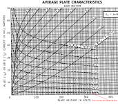
Take a look at the plate curves for a 12AT7 from the GE data sheet. Now imagine if the plate curves were pentode-like rather than triode-like, i.e. the curves flattened out rather than sloped upward. Now, take the family of pentode-like plate curves and mirror them vertically. You would essentially have the grid curves as shown in the graph. There would be almost perfect alignment with the existing grid curves, once they were converted to pentode-like curves.
So, if someone can figure out how to "pentodize" a triode's plate curves, it would be a simple matter of mirroring the results to match what the grid current actually does. Perhaps I am oversimplifying or missing something, but it seems quite doable to me.
The reason I believe there is a relationship between the tube mu, plate curves, and Ig, is because it makes sense, as you have alluded to above.
Take a look at the plate curves for a 12AT7 from the GE data sheet. Now imagine if the plate curves were pentode-like rather than triode-like, i.e. the curves flattened out rather than sloped upward. Now, take the family of pentode-like plate curves and mirror them vertically. You would essentially have the grid curves as shown in the graph. There would be almost perfect alignment with the existing grid curves, once they were converted to pentode-like curves.
So, if someone can figure out how to "pentodize" a triode's plate curves, it would be a simple matter of mirroring the results to match what the grid current actually does. Perhaps I am oversimplifying or missing something, but it seems quite doable to me.
Attachments
This relationship has already been investigated with some models made from the research results, try searching for Cohen & Helie, and Dempwolf & Zolzer.
Why? As the signal is coming from a high impedance source (previous anode) I would have thought you want to avoid grid current.karsten21 said:Taking some literature/schematics in account it's wise to bias the cathode follower less than 1v ( say 0.5 ) to let flow a small grid current from anode of gain stage.
Grid current, and its threshold voltage, can vary greatly from one valve sample to another and over the life of the valve. Don't rely on what a simulation shows you. Instead, design for no grid current - Vgk greater than 1V should ensure this for most samples.
They're talking about guitar amps. Strictly this thread ought to be in the musical instruments section.Why?
If a little distortion is not a problem then why worry about grid current at all? Grid current in a small signal stage is certainly not something to aim for (except when grid current bias is used) so if it can be ignored (as here) why aim to have it present?
I'm guessing the OP wants to simulate realistic clipping effects, maybe to look at the FFTs or overload recovery characteristics. Perhaps for academic reasons.If a little distortion is not a problem then why worry about grid current at all?
Here is a Rydel style grid current model for the 12AX7.
change from
bgg g k i=5e-6*(uramp(v(g,k)+0.2)^1.5)
to
bgg g k I=IF(V(G,K)>0, 5.10044246234457E-09 * ((( 4238.969348634 +V(A,K))/( 281.39443771702 +V(A,K)))**4)*V(G,K)**1.5,0)
This will gives grid current matching that I have measured in a 12AX7 some time ago.
Robert,
How does one come up with the parameters for this grid current model?
Could the parameters be a little off for the12AX7? Just found a post by jazbo where he compared a few models and they all show limiting at about 50V or so, compared to about 80V with your values.
- Status
- Not open for further replies.
- Home
- Amplifiers
- Tubes / Valves
- Spice model with grid current 12ax7