I am using Cat6 UTP solid core (wall mount) Ethernet cable as speaker cable, am I on the wrong track?
That is typically what i use… a pair od single strands pulled from the cable. Preferably teflon insulation & cryotreated.
dave
And a lot of speaker voice coils are CCAW. It actually makes the motor more efficient by reducing MMS. If you get a faster reduction in MMS than you lose effective (normalized) BL then the motor becomes more efficient.
Orange Home Depot extension cord wire is copper. And cheap, relatively speaking.
Orange Home Depot extension cord wire is copper. And cheap, relatively speaking.
Objective listening comparison.what kind of evidence do you need to just buy a piece of cable for $ 150-200?")
At the voltages the utility uses on their side of the transformer, the effects of inductance (at 60 Hz !) FAR exceed the effects of resistance. Even with a,uminum wire. So much so that in a 1st order power system analysis R is ignored in the transmission lines and transformers, but L is NOT.
Hmmm. My math on my 250V line and the utility company's 20,000 side suggests that (in residential districts) Capacitance counts for much more energy.
This sure is true on the crazy California megavolt lines.
On 500 feet of #2 Aluminum run at 250V nominal "100A", I figure resistance is the main reason my lamps dim when the pump kicks-in, and inductance (listed in wire-supplier data) (twisted trio) is a minor correction. I can't actually be happy sucking 100 Amps, because by 60A my house is down to 108V (~~0.3r per side). (I think it was wired for a 1980s trailer, and the house just happened without re-investing in power.) I can't see how ANY capacitance could matter on a 2.4 Ohm line at 60Hz. (Assumed 0.02uFd/500' @ 60Hz gives a huge shunt impedance.)
At HIGH impedance, series inductance tends to be minor, shunt capacitance major. But on my street, 10,000 feet @ 20kV/100A, 0.1uFd (spaced pair), we have 200 Ohms real and 2,700 Ohms capacitive reactance. My neighborhood is non-grid and if I extend this back 10 miles to the old dam I get say 40 Ohms R and 270 Ohms C, still no big deal. (These lines are probably design-limited by Corona in the salt air.)
In industrial districts, Induction motors dominate the energy flow with large lagging current. But all power suppliers bill large customers for reactive power, enough to justify customer capacitors.
I am using Cat6 UTP solid core (wall mount) Ethernet cable as speaker cable, am I on the wrong track?
Is it a joke?
For example, distribution transformers are made of copper wire and aluminum. Thus, the transformer coil made of aluminum has more dimensions to save power and reduce losses! Which in the end already increases the losses in the magnetic circuit. The strongest trend today, especially in China and Japan, is the use of an amorphous alloy magnetic core and copper wire in coils, and not vice versa.At the voltages the utility uses on their side of the transformer, the effects of inductance (at 60 Hz !) FAR exceed the effects of resistance. Even with a,uminum wire. So much so that in a 1st order power system analysis R is ignored in the transmission lines and transformers, but L is NOT.
That's right, and here a notary with confirmation of facts will not help and is not needed. You just need to buy to listen and compare the cables that you and your friends have in your audio system. This is what we do in Russia.Objective listening comparison.
Last edited:
Sort of, cryogenic treating is an even better one, yet to be explained.Is it a joke?
You can be on the right track and still be hit by a train.I am using Cat6 UTP solid core (wall mount) Ethernet cable as speaker cable, am I on the wrong track?
Alfred E. Newman.
I am using Cat6 UTP solid core (wall mount) Ethernet cable as speaker cable, am I on the wrong track?
IMHO yes. Many years ago i liked using CAT5 copper for internal wiring of preamps because of its cheapness and availability. This was before i realised how horrendously coloured even short lengths of it sounded. Perhaps this relates only to the specific types i have tried, never did an extensive research.
I find there is just no excuse for adopting any type of wire without doing at least a quick comparison test first. And this is no less important for audiophile approved wire.
If you think THD is useless then why not compare a 20% THD amp with a 0.01% THD amp? Of course, some will prefer 20% THD.planet10 said:Certainly a possible. But the fact that single number THD measures are basically useless in quantifing the sound could also be a BIG factor.
THD tells us something. To say that it tells us nothing is as daft as saying that it tells us everything.
Wide spacing means high inductance. In a speaker cable resistance dominates.wg_ski said:At the voltages the utility uses on their side of the transformer, the effects of inductance (at 60 Hz !) FAR exceed the effects of resistance. Even with a,uminum wire. So much so that in a 1st order power system analysis R is ignored in the transmission lines and transformers, but L is NOT.
IMHO yes. Many years ago i liked using CAT5 copper for internal wiring of preamps because of its cheapness and availability. This was before i realised how horrendously coloured even short lengths of it sounded. Perhaps this relates only to the specific types i have tried, never did an extensive research.
I find there is just no excuse for adopting any type of wire without doing at least a quick comparison test first. And this is no less important for audiophile approved wire.
Some fake Cat5 (ie fake Belden) is CCA. Afaik Cat5 is designed primarily for HF 10Mhz to 100Mhz but they work well up to 500Mhz.
For preamp, microphone cable might work better, something like Canare which is cheap and sounds pretty good.
@lclazar,
you're not on the wrong track, but ...
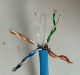
My experience ... I tried a single pair of Cat6 with wteflon insulation. Then I tried star-quad from Cat6; up and down pairs for postitive; laft and right pair for negative pole of speakers. That was so much better.
It was Cat 6 marked on the cable as: AVP UTP Cat6 FLUKE DTX-1800 Test F1 214M. It was copper wire with teflon insulation and PVC around the same as the inner cross insulation that holds the wires as a "solid" star-quad.
But I gave up CatXX a long time ago. Gotham star-quad speaker cable with polyolefin insulation is perfect for my 300B SET and fullrange with woofer and super twitter assistance.
Btw, all star-quad in my hifi works really perfect. I like it so much.
I'm sending a CAT6 image I used.
Just my IMO.
Best diying
you're not on the wrong track, but ...
My experience ... I tried a single pair of Cat6 with wteflon insulation. Then I tried star-quad from Cat6; up and down pairs for postitive; laft and right pair for negative pole of speakers. That was so much better.
It was Cat 6 marked on the cable as: AVP UTP Cat6 FLUKE DTX-1800 Test F1 214M. It was copper wire with teflon insulation and PVC around the same as the inner cross insulation that holds the wires as a "solid" star-quad.
But I gave up CatXX a long time ago. Gotham star-quad speaker cable with polyolefin insulation is perfect for my 300B SET and fullrange with woofer and super twitter assistance.
Btw, all star-quad in my hifi works really perfect. I like it so much.
I'm sending a CAT6 image I used.
Just my IMO.
Best diying
Attachments
Let's presume we're driving 4 ohm speakers. These draw a lot of current and are relatively hard to drive, compared to 8 ohm speakers. The speaker wire acts like a resistor. If we want 90% of the amplifier voltage to appear across the speaker then the wire should have no more than .4 ohms. Remember, the speaker wire carries the current there and back, so a 10 foot run of cable is 20 feet of wire. We have to double the resistance figures in the table above, as we're using 20 feet of wire to make a 10 foot cable. Looking at our table that means we need 24 gauge wire for a 10 foot run. We could use 26 gauge wire for a 5 foot run. Since the speaker gets 90% of the amplifier power, the cable is using up 10% and the cable effects are 20dB down. Let's consider another factor of 10, so that 1% of the power is dissipated across the speaker wire. Now for a 10 foot run the wire must be under .04 ohms and we need 14 gauge wire. With 14 gauge wire the speaker cable effects are down by 40dB. So a decent argument can be made that your speaker wires should be good quality 12 or 14 gauge wire. Let's use another factor of 3 and require our wire to have no more than .013 ohms on a 10 foot run. This puts the wire effects down by 50dB. Apparently we need about 8 gauge wire to accomplish this.
There are some points that make me scratch my head: 90% of amplifier voltage arriving at the speaker doesn't mean 90% of amplifier power. It's just 81% of that. To get 90% power there means 94.8% voltage. So cable losses need to be reduced to about 5%, which means 0.2 ohms DC resistance wrt to an impedance of 4 ohms.
But what does it really mean? Certainly we don't hear some 10% of power loss. Leaves the aspect of speaker damping. Here we have to consider that the voice coil's DC resistance, plus the woofer's LP filter inductor's resistance, always are in series with the cable. For a 4 ohms woofer, the VC's resistance certainly can be assumed to about 2.5 to 3 ohms, plus some tenths of ohms for the LP inductor, which swamp those 0.2 ohms completely.
Best regards!
RajkoM and all,
Thanks for the information, this is an interesting thread. I will experiment with various speaker cables if my tube monoblocks will be finished, and I will have some time.
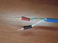
The cable I am using has the following written on it:
SCHRACK P/N HSEKP423HC CAT6 F/FTP 4x2xAWG23/1 LSOH TESTED TO 450MHZ NVP=79% 33/09
It is not UTP but STP (shielded twisted pair). See photo attached. For now it works well, but I am bitten by the upgrade bug like many of us. So I am looking other cheap alternatives.
@sesebe: it is not a joke, I don't run the cable in the wall. It is laid on the floor. Although it is rigid, it is quite manageable.
Thanks for the information, this is an interesting thread. I will experiment with various speaker cables if my tube monoblocks will be finished, and I will have some time.
The cable I am using has the following written on it:
SCHRACK P/N HSEKP423HC CAT6 F/FTP 4x2xAWG23/1 LSOH TESTED TO 450MHZ NVP=79% 33/09
It is not UTP but STP (shielded twisted pair). See photo attached. For now it works well, but I am bitten by the upgrade bug like many of us. So I am looking other cheap alternatives.
@sesebe: it is not a joke, I don't run the cable in the wall. It is laid on the floor. Although it is rigid, it is quite manageable.
Attachments
Last edited:
THD does "suggest" something. The Gedlee metric is an attempt at improvement (weighing harmonics by their audibility rather than simple level relative to fundamental), but it's still a single number. I've ranted in Blowtorch that there should be two numbers for distortion, one gives the relative level of the lower harmonics, the other for the remainder of the harmonics.If you think THD is useless then why not compare a 20% THD amp with a 0.01% THD amp? Of course, some will prefer 20% THD.
THD tells us something. To say that it tells us nothing is as daft as saying that it tells us everything.
The 20% number you give 'suggests' a SET amp that might actually sound good, even though it's not a good representation of the original signal. The 0.01% figure suggests a solid state amp with lots of feedback. With my method the first might give 20 and .2, and the second .03 and .09. But the 20% THD could as well be 15 and 16 in my system, indicating some bad clipping regardless of the amp type.
That's right, and here a notary with confirmation of facts will not help and is not needed. You just need to buy to listen and compare the cables that you and your friends have in your audio system. This is what we do in Russia.
That (bold) is subjective listening comparison.
Yeah, I thought the cryo treated audio cable fad was debunked 15 years ago. It's stunning to see it still alive on forum these days.Sort of, cryogenic treating is an even better one, yet to be explained.
Why do you need to compensate for skin effect in audio application?I personally prefer solid core cables in my system. Multiple runs of modest gauge wire per terminal seems a logical approach to avoid the small risk of skin effects.
I sense a closure happening soon.
Your spider sense is tingling again - funny how some of these threads are fated to an early demise.
How many angels can dance on the head of a pin? I dunno, how big is the pin?
- Status
- Not open for further replies.
- Home
- Member Areas
- The Lounge
- Speaker Wires, analysis and results