
The output mosfet..
BUK9Y15-100E,115..
are rated at 100V so i guess with a buffer 60...70 Volt should be okay .
BUK9Y15-100E,115..
are rated at 100V so i guess with a buffer 60...70 Volt should be okay .
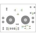
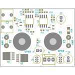
Hello jhofland, is the circuit unchanged from your 2018 post in this thread? (#333)I found the design and regenerated the BOM. I have attached it plus a front and back parts placement files.
Would you share the KiCad project, so I could work on a different version? - I would share the result here of course (if anyone can use it) 🙂
I would change the connection and mounting layout (so not for mounting on terminals), and also look at adding a flexible power supply section, that could directly accept typical amplifier voltage range (something like +/- 20 to 70v if possible).
Hi to all
i need your help please.
if i want to power up Jhoflands SSR its needed to supply it with +/- 7V(9) volts minimum so that the 78L05 and 79L05 can work easily.
i think about 9 V AC/DC converter by meanwell IRM-01-9.
here it is:
do i get any problems if i use 2 of these and build in the middle the GND for the SSR PCB? i do not expect...or?
ps :
what is the power consumption of one pcb?
kr
chris
Hi chermann, I don't know if you can make a symmetrical supply from those AC/DC converters, but in any case, it seems a bit like "overkill" to me - there is a lot of components inside those converter modules, and I assume you already have +/- DC in the amplifier.
I think the power consumption of the SSR board is low enough, that you can just do a simple resistor divider based of your DC power rails. If e.g. you have +/- 50v rails, you just need four resistors to get around +/- 10-12v for the SSR board.
Once you have the SSR boards, you can measure the power consumption, and then do a precise resistor divider calculation.
Edit: Perhaps best to start a seperate thread regarding jhofland's SSR module etc, since this thread is meant for the official Diyaudio boards 🙂
hi Jvhb
i never ever use a resistor divider for constant voltage! - a 7812/7912 will do. yes i do not expect a hugh current so no power problems.
yes start a new thread, i am happy without updates but your work will be interesting!
post here the link
kr
chris
i never ever use a resistor divider for constant voltage! - a 7812/7912 will do. yes i do not expect a hugh current so no power problems.
yes start a new thread, i am happy without updates but your work will be interesting!
post here the link
kr
chris
I have just installed the DC protector board in an F5M and struggling with odd behaviour from the board. This is my first amp build, so am learning as I go.
It is powered off an 18V secondary, and with no connection to the amp or speakers (power only), it behaves normally. LED 1 lights solid, LED2 flickers for a few seconds before the relay clicks and LED2 lights solid. I can confirm connectivity between IN and SPK at this point on both channels.
However, if I wire up the amps, LED2 flickers continuously and the relay never engages.
Running the amp as normal (bypassing the DC protect board), I am at 0-20mV DC offset (I'm not sure that means anything, but just in case)
Help!
You need to check your 18 volt power supply grounds are correctly configured.
Is this a separate and floating 18 volt secondary or is it used for the amp as well?
The supply for the board needs to be ground referenced to the main ground in the amp it is protecting. In other words ground on the protection board must be connected the main ground in the amp. Make sure that is all correct.
Brilliant, thanks @Mooly - that makes sense, but I'm not sure how to do that in practice.
The secondary is used for the amp too. I am running each (2 of) 18V secondary to a rectifier. I'm currently tapping off the AC side of the rectifier of one of them across to the DC Protector (to +V and G).
Should I be running +V off the secondary and ground via the Powersupply board?
The secondary is used for the amp too. I am running each (2 of) 18V secondary to a rectifier. I'm currently tapping off the AC side of the rectifier of one of them across to the DC Protector (to +V and G).
Should I be running +V off the secondary and ground via the Powersupply board?
Switch the amp off and check you have direct continuity from the protection board to the amp ground.
That sounds OK. You need to tap off the secondary that supplies the positive rail (assuming you are using the F5 PSU). Check the supply to the protection board is correct when the amp is on.

I'm currently tapping off the AC side of the rectifier of one of them across to the DC Protector (to +V and G).
That sounds OK. You need to tap off the secondary that supplies the positive rail (assuming you are using the F5 PSU). Check the supply to the protection board is correct when the amp is on.
Confirming I have no continuity from the board to amp ground, and I am running AC power off the secondary supplying Rectifier B. Will shifting the power over to Rectifier A resolve the grounding issue?Switch the amp off and check you have direct continuity from the protection board to the amp ground.
The ground must be like this, otherwise the board has no 0v reference to work to to determine if there is an offset or not.
If each transformer secondary is 18 volt then the DC rail value will be around 24 to 25 volts which means the board needs 12 volt relays (2 in series = 24 volt).

If each transformer secondary is 18 volt then the DC rail value will be around 24 to 25 volts which means the board needs 12 volt relays (2 in series = 24 volt).
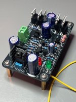
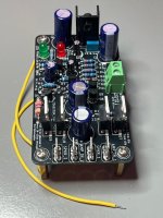
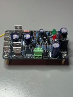
@prasi --- I just built up the first SSR Delay/Protect board of your design. Thanks for sharing, the spacing, hole size and soldering was easy.Hello has anyone built the SSR protect based on diya I posted a while back. I haven't been following this , so just wanted to know if there any updates.
Thanks
Prasi
So far I have tested it on the bench with 15V power and 1-3V DC on the output and it worked perfectly as expected. Delay is ~7 seconds, with a fast turn-off and turn-on and it was ~5 seconds, but with more than 10 seconds between power-off to power-on it is ~7 seconds delay every time.
With 1-3Vdc on the AMP_IN it takes about <0.5 sec to trigger and disconnect the AMP-IN from SPKR connections. Once you remove the DC the delay is ~7 seconds and the protection is back protecting your speakers.
Couple observations:
1) LED1_DELAY - flickers/blinks during power-on delay period and when protection is triggered --- is that normal? I am using a RED LED, not the schematics Yellow, but might be my testing on the bench.
2) The TO-220 Mosfet holes in the PCB are slightly to far apart (see picture) - not a big issue, but does require some force and bending the legs to get them in, but maybe JLCPCB messed up my board order, who knows.
3) I'm not great at parts finding, so the bridge rectifier (B2) part # was not in the BOM or Schematic - so I took a gamble with a DF04M (400V 1A) and it fit perfectly in case someone else is not sure what to order.
Attachments
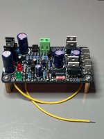
Follow up after some more testing -
I'm using a small transformer 10w encapsulated transformer, from a switching PSU standby circuit. It outputs 15.43Vac, and after turn-on measuring at the AC input connector on the SSR board, drops to 14.84Vac.
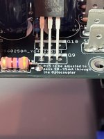
R15 change needed:
With the standard 470r resistor in R15, I was seeing 9.17Vdc across or 19.5mA going to the optocoupler. So I changed R15 to 390r, and now I'm seeing 9.14Vdc across the resistor, or 23.5mA to the optocoupler. Not sure the 470r resistor had any ill effects, because they operate the same, with either 470r or 390r.
I'm using a small transformer 10w encapsulated transformer, from a switching PSU standby circuit. It outputs 15.43Vac, and after turn-on measuring at the AC input connector on the SSR board, drops to 14.84Vac.
R15 change needed:
With the standard 470r resistor in R15, I was seeing 9.17Vdc across or 19.5mA going to the optocoupler. So I changed R15 to 390r, and now I'm seeing 9.14Vdc across the resistor, or 23.5mA to the optocoupler. Not sure the 470r resistor had any ill effects, because they operate the same, with either 470r or 390r.
- Home
- The diyAudio Store
- Speaker Turn On Delay and DC Protector Board Set (V3)