Prasi,you know the next step!😉
I hope this is the expected next step😉.
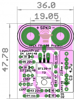
edit: slightly edited the silk (credits)
Attachments
Last edited:
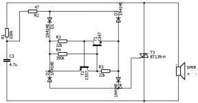
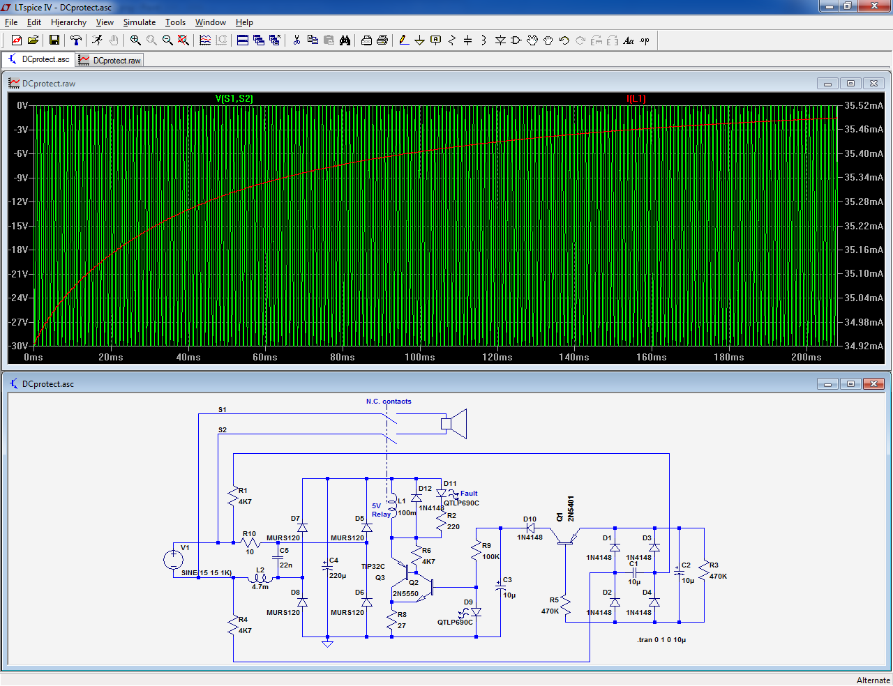
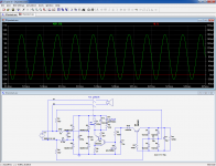
Here is an idea of passive circuit, based on a normally-closed relay avoiding further damages to the amplifier in the event of a fault:
Under normal conditions (no DC), the relay remains unenergized:
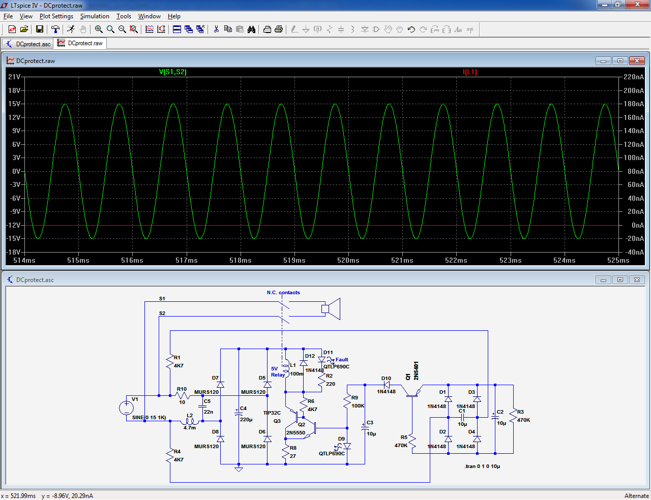
When DC is present, the relay is activated, opening its contacts:
Under normal conditions (no DC), the relay remains unenergized:
When DC is present, the relay is activated, opening its contacts:
Attachments
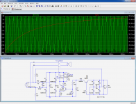
Good,very clever design! but in this case you need another mute circuit elsewhere ,maybe in the amplifier input.Here is an idea of passive circuit, based on a normally-closed relay avoiding further damages to the amplifier in the event of a fault:
Under normal conditions (no DC), the relay remains unenergized:
When DC is present, the relay is activated, opening its contacts:
Is it a pcb available?
Last edited:
Why? This might be required for the previous examples, the ones shorting the output (although it risks being ineffective, if the amp's problem is such that it is completely unresponsive), but this ones opens the speaker's circuit all the time the voltage is present. In fact, the fault voltage serves to power the circuit.Good,very clever design! but in this case you need another mute circuit elsewhere ,maybe in the amplifier input.
No, I just cooked it now, it's still hot from the oven and hasn't been tested.Is it a pcb available?
Another possibility would be to drive a bistable relay, but the rearming problem would need to be solved.
An elegant method would be to use a purely electromechanical residual current circuit breaker: there is a manual resetting lever that could be accessible on the rear of the speaker
Member
Joined 2009
Paid Member
Elvee, this is the approach I was looking to achieve with depletion mode FETs so that it could be a SS relay. Perhaps with multple FETs in parallel the on resistance could be tamed?
As a normally-closed relay used how the start-up noise will be avoided?Why? This might be required for the previous examples, the ones shorting the output (although it risks being ineffective, if the amp's problem is such that it is completely unresponsive), but this ones opens the speaker's circuit all the time the voltage is present. In fact, the fault voltage serves to power the circuit.
No, I just cooked it now, it's still hot from the oven and hasn't been tested.
Another possibility would be to drive a bistable relay, but the rearming problem would need to be solved.
An elegant method would be to use a purely electromechanical residual current circuit breaker: there is a manual resetting lever that could be accessible on the rear of the speaker
Last edited:
Member
Joined 2009
Paid Member
Indeed: this thread is about speaker protection, not anti-thump circuits, and anyway, how would the circuit know what is a power-on thump and what is part of the program, like violent percussions, explosion noise, etc?Let the amp builder handle that. A passive speaker protect has value by itself.
Continuous DC for more than ~100ms is clearly pathological, but other than that....?
Member
Joined 2009
Paid Member
Perhaps with multple FETs in parallel the on resistance could be tamed?
Digikey carries the CPC3902 depletion FET. There's a price break at 25 and they're not expensive so we put 25 of them in parallel.
This would provide an effective on resistance of ~<0.1R, carry a pulse current capability of ~10A.
They'd be 'normally closed' and a dc-fault would be used to energize them.
Yeah, they even become dirt cheap by >10K, so let's place a group order😀Digikey carries the CPC3902 depletion FET. There's a price break at 25 and they're not expensive so we put 25 of them in parallel.
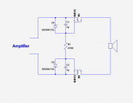
The circuit could be made remarkably simple and elegant:
Attachments
Member
Joined 2009
Paid Member
A small pcb could be very popular. Why not wait a bit and the eBay folks in China will have one ready at very low prices ?
I have some DN2540's on hand. Would they work for a quick test? This could be a boon for small headphone amps needing a passive and reliable protect. with some headphone amps you want a little resistance in normal operation.
Last edited:
Member
Joined 2009
Paid Member
If you can tolerate the on-resistance they would be fine. It would be interesting to just stick one of those FETs, unpowered, into the output signal and see if the inherent resistance is linear enough to not impact the sound.
Last edited:
Probably two in parallel would be 13ohms is fine for headphone amp as I have 10ohm in series now. What keeps the FET from motor boating under certain music passages?
Member
Joined 2009
Paid Member
motor boating? well the dc-protection should be set up to ignore low frequency music, of course there must be a corner frequency somewhere but generally I've not heard of people finding this a limitation with speaker protection circuits. Suck it and see.
I like schematic from Elvee, i m not so experienced but i think something similar..
Loudspeaker Peak Indicator Circuit
but instead of led to put relay for 5v (it consuption something about 60ma) and to change R9 maybe also to correct value of C1
Loudspeaker Peak Indicator Circuit
but instead of led to put relay for 5v (it consuption something about 60ma) and to change R9 maybe also to correct value of C1
Last edited:
OR even better
Australian Technical Production Services
just to put trimpot in place of R6 and delete high passs filter
Australian Technical Production Services
just to put trimpot in place of R6 and delete high passs filter
- Home
- Amplifiers
- Solid State
- speaker protection