Hi, Timios!Thanks,probably in the past...
You didn't connect the A.C detection,C2 not charged.
You didn't connect amplifier out,C5,6 not charged.
That's why you seen different voltages.
The order was two weeks ago, indeed.
The testing was described as shown in the attachment. Maybe I understood it wrong?
Hi Bonsai, I'm building a Class A amp that has +/-20V rails, can your board work down to 20V? Thanks
Ed,
the maximum voltage you can input to pin 4 is 10V. The trigger level on pin 4 (AC ON/OFF detect input is between ~0.6 and ~0.8V
So, I'd say you are ok with your protection board.
the maximum voltage you can input to pin 4 is 10V. The trigger level on pin 4 (AC ON/OFF detect input is between ~0.6 and ~0.8V
So, I'd say you are ok with your protection board.
Hi Bonsai, a couple of questions regarding this cct.
what is the purpose of R12 and R13? antifloat?
some other designs i have seen use a pair of diodes at "speaker out" going to the psu rails?
what is the purpose of R12 and R13? antifloat?
some other designs i have seen use a pair of diodes at "speaker out" going to the psu rails?
Thimios, the TLP191 is discontinued.
However, the TLP3906 should also work https://www.mouser.co.uk/datasheet/2/408/TLP3906_datasheet_en_20191222-1916273.pdf also avaiablle from RS here https://uk.rs-online.com/web/p/optocouplers/1250602?sra=pmpn
Hope this helps
🙂
However, the TLP3906 should also work https://www.mouser.co.uk/datasheet/2/408/TLP3906_datasheet_en_20191222-1916273.pdf also avaiablle from RS here https://uk.rs-online.com/web/p/optocouplers/1250602?sra=pmpn
Hope this helps
🙂
ctrlxHi Bonsai, a couple of questions regarding this cct.
what is the purpose of R12 and R13? antifloat?
some other designs i have seen use a pair of diodes at "speaker out" going to the psu rails?
yes - this is to tie the inputs down - The DC detect input is taken from the amplifier side. If this is floating during test etc you may get problems so that's why I tied then down with the 12k resistors.
Re the diodes going to the rails, this is usually done to deal with the back EMF of the loudspeaker that can under certain circumstances push the amplifier output voltage above the supply rails and cause damage. I use these diodes on the output of my big bipolar amplifiers, but I do not have them on the sx, nx or kx2 amplifiers and have not run into any problems. If you are worried about this, then you can add them from the speaker side of the SSR to the amplifier supply rails. The diodes only need to be rated for peak short term currents, so a 3A device will be ok since it will handle very high single shot currents which is what you are protecting from.
Note, with mosfet output stage you do not need these diodes, since the body drain diode does that job for you.
Yes - there will be some resistor value changes, but it will work.Hi Bonsai, I'm building a Class A amp that has +/-20V rails, can your board work down to 20V? Thanks

You have been realy busy today with answering all those questions.Ed,
the maximum voltage you can input to pin 4 is 10V. The trigger level on pin 4 (AC ON/OFF detect input is between ~0.6 and ~0.8V
So, I'd say you are ok with your protection board.
I am glad with your answer to mine.
Regards,
Ed
Thanks Bonsai!Thimios, the TLP191 is discontinued.
However, the TLP3906 should also work https://www.mouser.co.uk/datasheet/2/408/TLP3906_datasheet_en_20191222-1916273.pdf also avaiablle from RS here https://uk.rs-online.com/web/p/optocouplers/1250602?sra=pmpn
Hope this helps
🙂
4.121 in stock at Mouser.
👍👍Thanks Bonsai!
4.121 in stock at Mouser.
It would be great if you could post the changes for me some time so I can build the PCB up. Thanks!Yes - there will be some resistor value changes, but it will work.
Already down to 2715, better hurry.Thanks Bonsai!
4.121 in stock at Mouser.
@Bonsai Can you explain how to figure the value of R9 and R10 for the Current Overload Detection Circuit using an opticoupler? I have 72 volt rails, so I'm gathering R11 would be increased to about 36k. If I was to use a 5V source in the amp of course it would be lower. Would TLP241B(d4,F work for the 72 volt rails? If I use the 5 volt source I would find a different opticoupler. I'm building Wolverine mono blocks, it should have 240 watts continuous into 8 ohms and 430 watts continuous into 4 ohms, it mentions 6 amp fuse per rail is minimum. It is using .21 ohm resistors for the emitter degeneration resistors.
Hi Bonsai!Ed, the board does not need anything special to work - it will work fine with your amp.
🙂 👍
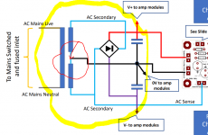
If you look at the scematic of the power supply in #105, you see it is a split one. Split secondairies. How do I connect the AC lines, plus, minus and ground, to the board? And the AC sense?
Should I just use the lines of ONE of the two channels?
It is not allowed to tie both secondairies together.....
It is still not very clear to me.
Thanks, Ed.
Ed, did you down load the Speaker Protection Board presentation?
Please see link below especially slide 8 - if still not clear let me know.
https://hifisonix.com/wordpress/wp-content/uploads/2022/11/Speaker-Protection-Board.pdf
Rgds
Andrew
Please see link below especially slide 8 - if still not clear let me know.
https://hifisonix.com/wordpress/wp-content/uploads/2022/11/Speaker-Protection-Board.pdf
Rgds
Andrew
Hi Andrew!
I did read the presentation. It shows one channel . My two channel amp (#105) has two separated and isolated secondary windings.
My Q is: Can I just use the connections of one channel to make things work?
And do I need the AC sense connection? I only want speaker protection.
Thank you, Ed
I did read the presentation. It shows one channel . My two channel amp (#105) has two separated and isolated secondary windings.
My Q is: Can I just use the connections of one channel to make things work?
And do I need the AC sense connection? I only want speaker protection.
Thank you, Ed
Last edited:
Hi Andrew!
I did read the presentation. It shows one channel . My two channel amp (#105) has two separated and isolated secondary windings.
My Q is: Can I just use the connections of one channel to make things work?
And do I need the AC sense connection? I only want speaker protection.
Thank you, Ed
Attachments
ed,
you only need one AC detect signal, so its ok to take it off just one of the secondaries. All the protector board is doing is looking to see if AC is present - it gives a long speaker switch-on delay when AC is applied but a quick one when the AC is removed. The AC detection is used to prevent speaker ON/OFF thumps when you power your amp up or down. I will add a short note about this in the presentation when I next do a site update.
If you are using completely separate +- supplies for each amplifier (i.e. monobloc construction) you can also just take the +- supply to the protection board off 1 amplifier power supply provided the two amplifiers share the same 0V. This will typically be the case if the amplifier 0V are connected to the chassis for safety, or, if the input signal grounds are joined together at the input socket and the amplifier main 0V goes to the chassis via a ground lifter. If the two amplifier channels 0V's are not joined in any way, you will need to use a separate Speaker Protection board for each channel
Last edited:
Hi Andrew, again!
My amp has a common 0.
So what I did is as you advised.
Plus and minus of one channel. AC detect from that same channel and the null.
And gess what? The thing works perfectly!
Thanks for your help, regards,
Ed
PS: I can read a book with the light of the Led! Hahaha.
My amp has a common 0.
So what I did is as you advised.
Plus and minus of one channel. AC detect from that same channel and the null.
And gess what? The thing works perfectly!
Thanks for your help, regards,
Ed
PS: I can read a book with the light of the Led! Hahaha.
- Home
- Amplifiers
- Solid State
- Speaker Protection Board