Well, you have been singularly unsuccessful so far refuting my case. And then conceding my point regarding broken or unconnected strands and after that still insisting that interstrand rectification will never have any audible effect is, shall we say, less than compelling.
Sorry. Didn't mean to ruffle feathers here. Just trying to explore a physical possibility which correlates with what I hear - when experimentally I pulled a hundred fifty feet of typical 'audiophile' stranded speaker cable from my HT system and replaced with solid conductor that had oxygen tight insulation, I would have put the stranded back if I hadn't heard a significant improvement because the stranded was certainly more convenient to use.
There is a difference between the diode theory of distortion and the distortion that is measured. Green copper wire will show more distortion. It just has not been shown to do with diode formation.
Dear Ed,
If it is not "micro diodes" (I always felt this explanation was unlikely, but investigation is difficult), how does copper oxide cause the rise in HD?
I'd be interesting in a better explanation. Do you have one?
Ciao T
There is a difference between the diode theory of distortion and the distortion that is measured. Green copper wire will show more distortion. It just has not been shown to do with diode formation.
If it is not "micro diodes" (I always felt this explanation was unlikely, but investigation is difficult), how does copper oxide cause the rise in HD?
I'd be interesting in a better explanation. Do you have one?
Ciao T
Dear Ed,
If it is not "micro diodes" (I always felt this explanation was unlikely, but investigation is difficult), how does copper oxide cause the rise in HD?
I'd be interesting in a better explanation. Do you have one?
Ciao T
Working on it, very slowly. Will present it when it is a formed and test idea.
Hi,
Actually, I would think as this is DIYA most make their own cables, especially as it is so easy.
So the question what makes "good" cables remains and there is no need to get all huffy and puffy about someone making obscene amounts of money (next to making money of russian oligarchs and chinese nouveau riche who buy HiFI's as decoration making a single buck of a DIY'er is really hard work)...
I do use fairly exotic cables (home made of course, with that even goldplated silver wire in air dielectric is very affordable and preferable to using cotton as some insist on doing) and I have found that audible differences do exist among different cables.
I am unsure if my gold-plated silver special is really better than (say) the better RG-XXX/Mil types with silverplated double screens as interconnects, but I like to use them anyway, because I have them. Same for my SCSI III based speaker cables, which may not be better than Cat 5 based stuff, but I have them and they look cool.
TBH, I really do not like the fact that cables make a difference, but I am even more appalled that people who should know better, keep trying to talk these differences away, especially those difference that are trivial to explain using basic electrical theory...
Maybe it has to do with an incident in my past, when many moons past I was living in a little charming country behind seven seas, seven mountains and one large wall, at which any that wished to leave said charming little country for the appalling capitalist west after having been taking in by all the glitzy slick advertising where promptly and summarily shot dead to protect them from such ignoble and terrible a faith...
By day I worked in a steelwork in the process control electronics section. By night I worked as sound engineer with a band (and DJ). As customary in those parts at the time, the band owned their own PA System, or more precisely, I owned most of it.
One day I needed a new, quite long microphone cable and lacked the time to drive to the only shop in the whole country that had the necessary imported stuff for Dollars (we bought our speaker drivers as well as a lot of other stuff there).
So I liberated some cable intended for sensors (to be precise, strain gauge sensors) from a large reel we had (cables kept getting damaged by liquid steel when people where careless, which they where often) and stole the XLR cables of some short old cables we no longer used. After a few gigs testing reliability I put the cable on our singers Mike. Our singer quite liked that cable was a little stiffer than the normal stuff (she liked a lot of things a bit stiff I guess) and a fetching bright orange.
For month afterwards I was really foxed that the singers mike sounded different, not neccesarily better or worse, but different and I had to compensate the settings for the mix subtly from what I normally was able to use.
I never in my dreams thought to consider the cable the culprit, after all, it's just a cable and it was similar in geometry, much better shielded than the normal mike cable I used everywhere and should really be no worse (maybe it was actually better, but this too I could not conceive at the time).
One night I put different cable on that Mike, I cannot remember why, but bang, the original sound was back. So I thought I must have been imagining things (I still had not twigged that I had in fact changed cables), but when at the following gig thing where back to different, so I dug down and finally identified the cable as culprit.
FWIW, the "offending" cable used silverplated copper conductors in some PTFE like stuff, a little softer than PTFE, it was twin twisted pair, had several rope inserts to make it more resilient when stretched, had a conductive rubber layer over this against triboelectric effects and used a foil screen with a dense silverplated copper screen, outer jacked was silicone rubber.
The normal cable was plain copper twin twisted pair with PVC insulation and a not too dense copper screen. Length was similar and >> 10m, but I would not say identical to the cm.
Mike was a Beta58 from Shure, mixing desk was an east german design which included exemplary RF Filtering and transformer inputs for all inputs. Mikes and instrument feeds connected to a stagebox to which a "snake" made from shielded, gel-filled telephone cable was connected with a multi-pin plug (same plug was also fitted at the Mixer flightcase), the snake was either 25m or 50m.
Since this very annoying cable demonstrated to me so clearly that the "it's all wire" view I learned at university clearly did not cover all there was between heaven and earth, I have held a solid disrespect for any position that attempts to maintain this overly simplistic and inaccurate view as true.
I have in the intervening decades learned a lot about why things that should, on casual inspection with EE's eye, not sound different actually do so anyway. And rarely do I have to accept that the reasons are inscrutable or require very esotheric explanations...
But for those who want to wilfully blind, please keep it up.
Ciao T
PS, FWIW, when the reel at work was used up (I liberated no more of this one cable of course, I might have even taken the cable back as I did not want it) the company declined to buy a new imported reel for these ridiculous levels of money and we used afterwards locally made stuff that looked identical enough.
After month of ongoing minor but annoying and costly malfunctions in the systems that had been patched with this "cheap" cable the US Supplier of the whole system was called in. They looked around and found not much, until they looked at the patched cables and asked "WTF is THAT".
The correct cable was purchased and fitted and was well again in this little corner of the world, untill people made a revolution a few years later, imported capitalism and the steelwork shut down leaving thousands out of work, but that, as they say is another story.
+10 and lovely story .... anymore ?.......... 🙂
Hi,
Well, there was this one time I made my own Nitro. I was REALLY young then and VERY stupid, I still have two hands and all fingers, but more by luck than skill... Well, I knew how to make it, could get the ingrediences (actually the acid part was the interesting one), so why not I thought?
I also once had the job of redesigning modules for a studio mixing desk (same small country, these consoles where in all the studios, TV, Radio, recording), originally real classic discrete transistor circuitry, near spitting image of Neve.
Being young, foolish and fresh from being told Op-Amp's are the next big thing I used them extensively. Three month work. The prototype measured SO GREAT, we all where VERY exited. It sounded so BAD, it was spectacular...
Anyway, those where fun times.
Much of what I did then is no longer possible these days, maybe the world is worse off for it, maybe not...
Ciao T
lovely story .... anymore ?.......... 🙂
Well, there was this one time I made my own Nitro. I was REALLY young then and VERY stupid, I still have two hands and all fingers, but more by luck than skill... Well, I knew how to make it, could get the ingrediences (actually the acid part was the interesting one), so why not I thought?
I also once had the job of redesigning modules for a studio mixing desk (same small country, these consoles where in all the studios, TV, Radio, recording), originally real classic discrete transistor circuitry, near spitting image of Neve.
Being young, foolish and fresh from being told Op-Amp's are the next big thing I used them extensively. Three month work. The prototype measured SO GREAT, we all where VERY exited. It sounded so BAD, it was spectacular...
Anyway, those where fun times.
Much of what I did then is no longer possible these days, maybe the world is worse off for it, maybe not...
Ciao T
Hi,
Yes, it is a bad arguments, the earth has been shown to be spherical in europe since around 2400 Years ago. I am sorry, but your are just completely making things up to support an untenable position.
If you have to ask, please retake EE101... I am not offering free remidals.
Here you go on again about money. I think this is getting quite silly here...
Ministry of Silly Walks - YouTube
Money is nothing in this issue. If you want to talk abount money your should join Congress or Senate...
Really. Interesting. Or maybe they DO have these problems and your will yourself to not hear them? One would have to, ahhhmmmm, measure, to be sure, subjective assessments really cannot be trusted all that much now, can they now?
That is fair enough. Then you should realise that others may have differing experiences and results. YMMV.
I have not mentioned wires, honestly, what is it with that fixation?
Ciao T
Re ground loops;
"If you have to ask, please retake EE101... I am not offering free remidals."
As luck would have it I wrote the acceptance testing procedure for isolated ground (star ground) systems for the largest research consortium in the world. I don't need to take the course, I could teach it.
If you think there is any skin effect on cables at audio frequencies I'm afraid you need to go back to basic radio text books and re-read them 😉Changes in skin effect is another way surface oxidation of copper affects its signal conduction quality. I'm talking about all types in aggregate, not just cuprous oxide, so nobody try to pounce on that and claim I'm contradicting myself. Of course, if one insists skin effect can have no effect on SQ, why even use multistrand wire in the first place? It's all the same, right?
Depending on the cable type, skin effects don't become measurable until somewhere on the order of 1Mhz, some 50 times higher than the highest audio frequency. Skin effect at audio frequencies is a myth.
Low frequency cables are made multi-stranded for flexibility and resistance to fracturing from repeated bending, not any skin effect.
Last edited:
signal degradation
If a mechanism exists, and HD increase is real, could be many things... thermal degradation causing non-linear resisitivity changes, variable moisture content of the carbonate/oxide surface, etc...
micro-diodes... not likely
Dear Ed,
If it is not "micro diodes" (I always felt this explanation was unlikely, but investigation is difficult), how does copper oxide cause the rise in HD?
I'd be interesting in a better explanation. Do you have one?
Ciao T
If a mechanism exists, and HD increase is real, could be many things... thermal degradation causing non-linear resisitivity changes, variable moisture content of the carbonate/oxide surface, etc...
micro-diodes... not likely
Simon, skin effect at very high audio frequencies can be readily measured. It's pretty darn low, but it is there. In another thread, I ran a few numbers showing that, for a typical speaker, the frequency response change was in the sub 0.1dB region at 20kHz. With an amplifier having a moderate source impedance, it drops to 63% of F-all.
edit: If you go to Audio Critic's website, in one of their back issues they did some frequency response calculations for various cables. You can see that most of the HF loss comes from cable inductance and in some cases may be large enough to be audible.
edit: If you go to Audio Critic's website, in one of their back issues they did some frequency response calculations for various cables. You can see that most of the HF loss comes from cable inductance and in some cases may be large enough to be audible.
Indeed.If a mechanism exists, and HD increase is real, could be many things... thermal degradation causing non-linear resisitivity changes, variable moisture content of the carbonate/oxide surface, etc...
Any series resistance that changes in value with current flow and which has a thermal time constant that is short relative to an AC cycle will add 3rd harmonic distortion to a waveform.
The classic example is the amplitude stabilisation bulb or thermistor used in the feedback network of a wein bridge oscillator. It's used as a PTC such that if the output amplitude tries to increase the bulb heats up, increases in resistance, increasing negative feedback thus stabilising the output.
To work properly the bulb has to have a long thermal time constant relative to the AC waveform so that it's not significantly changing in value during an individual cycle. If the bulb is too small or the operating frequency is too low, distortion is added.
Wien bridge oscillator - Wikipedia, the free encyclopedia
"The resistance of light bulbs and similar heating elements increases as their temperature increases. If the oscillation frequency is significantly higher than the thermal time constant of the heating element, the radiated power is proportional to the oscillator power."
"At lower frequencies the time period of the oscillator approaches the thermal time constant of the thermistor element and the output distortion starts to rise significantly."
A small spec of contact area on for example an oxidised wire in a screw connector can be just such a PTC. The higher it's resistance the more localised heating for a given current, and the smaller it's size the quicker it's thermal time constant.
Whilst it would probably only generate harmonic distortion at bass frequencies (since the thermal time constant would still be too slow for mid/treble frequencies) the modulation of the resistance value with a high amplitude low frequency bass waveform would also modulate the amplitude of midrange and treble frequencies - essentially AM modulation, with a similar effect to AM modulation of high frequencies in a driver producing significant bass excursion.
Even in a multi-way passive crossover design, if the poor contact was before the crossover it could in theory still generate IM distortion between the bass and midrange, even if they are being handled by different drivers...
Last edited:
Before you edited I was about to ask if you were sure what you measured wasn't just very slight low pass filtering from the lumped inductance and capacitance of the cable... 🙂Simon, skin effect at very high audio frequencies can be readily measured. It's pretty darn low, but it is there. In another thread, I ran a few numbers showing that, for a typical speaker, the frequency response change was in the sub 0.1dB region at 20kHz. With an amplifier having a moderate source impedance, it drops to 63% of F-all.
edit: If you go to Audio Critic's website, in one of their back issues they did some frequency response calculations for various cables. You can see that most of the HF loss comes from cable inductance and in some cases may be large enough to be audible.
That's another good thing about conservatively sizing the cable gauge - larger cross sectional area doesn't just reduce resistance, it also reduces inductance...
Last edited:
If it is not "micro diodes" (I always felt this explanation was unlikely, but investigation is difficult), how does copper oxide cause the rise in HD?
I'd be interesting in a better explanation. Do you have one?
Ciao T
My double Lincoln...
The internal inductance of a cylindrical conductor is 15 nH per foot, given uniform current density profile. As frequency goes up, this inductance begins to lower as a result of skinning.
Skinning requires interstrand conductivity..without that conductivity, the Lenz effect does not happen (like litz), there will be diminished magnetic field exclusion. If this conductivity is non linear, bad things can happen at frequency.
Skin effect at audio frequencies is a myth.
I love those blanket assertions...
Cheers, John
Attachments
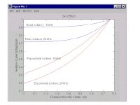
18 Gauge wire skin effect starts in theory at 17khz. (American Wire Gauge table and AWG Electrical Current Load Limits with skin depth frequencies) As I would like my amplifier to have less than 5 degrees of phase shift at 20khz with a back voltage from the tweeter of 10% and a damping factor of say 20 then I would like to see 32 gauge wire used. (Twisted to make say 10 gauge.) I settled on 28 gauge as that is easier to make. See http://www.westpenn-wpw.com/pdfs/cm_PDF/25210.pdf
John we just cross posted on the same thing!
John we just cross posted on the same thing!
That's another good thing about conservatively sizing the cable gauge - larger cross sectional area doesn't just reduce resistance, it also reduces inductance...
Actually, larger cross sectional area does not reduce inductance. the inductance of any cylindrical cross section of conductor is 15 nH per foot. The only way the larger wire can reduce inductance is....wait for it...wait for it...
Skin effect..
Perhaps we should call you....number 1? I'll play the part of Harcourt Fentin Mudd..😀
Cheers, John
An externally hosted image should be here but it was not working when we last tested it.
Simon, I did a quick and dirty calculation again. Assume a 15 foot run (30 ft here-and-back). The skin effect from a #12 solid conductor will drop the response by about 0.15dB at 20kHz. Using an extension cord like I have, with coarse strands, the drop is quite a bit lower, more like 0.05dB.
This will not keep me up at night worrying.😀
This will not keep me up at night worrying.😀
Sigh. 🙄 You might want to check your facts before making such bold claims.Actually, larger cross sectional area does not reduce inductance. the inductance of any cylindrical cross section of conductor is 15 nH per foot. The only way the larger wire can reduce inductance is....wait for it...wait for it...
Skin effect..
Wire diameter does affect it's inductance, anyone who has built UHF or microwave equipment knows this. For example the width of the track on a strip line filter affects its inductance. (As well as it's length)
The change is relatively small though. See the following:
Martin E. Meserve - K7MEM - Inductance of a Straight, Non-magnetic Wire, In Free Space
Notice the radius term in the equation.
You'll also find a similar formula for calculating inductance of a "straight wire conductor" 2/3 of the way down the wikipedia article:
Inductor - Wikipedia, the free encyclopedia
Again, notice the diameter term in the equation.
Now try to tell me again that inductance per foot is independent of wire diameter 🙄
Furthermore, while inductance does change slightly (a few percent at most) due to skin effect with with increasing frequency, the vast majority of skin effect at radio frequencies is an increase in resistance not a change of inductance.
The reason for this is that as the field no longer penetrates to the centre of the wire the effective cross sectional area of the wire progressively reduces until at some high frequency only the very surface is conductive, so the effective resistance can be many times the DC resistance, especially if the surface is oxidised.
This is why wire based antennas are often silver plated, (as silver oxide is still a good conductor) and why self supporting antennas are made from tubing rather than solid rod. (Since the centre of a solid rod is dead weight at radio frequencies that does nothing useful...)
I still maintain that skin effect is a non-issue at audio frequencies.
Last edited:
Inductance can be increased in twin lead by separating them. Further apart inductance increases, capacitance decreases. Bring them closer it's the other way around. How fortunate twin leads have such inherently low inductance and capacitance that the phone company can trasnmit DSL one whole mile from a central office. Now what is that about your 30 feet of speaker cable, how many nanohenries does it have and how many GHz is the 3db down point?
Sigh. 🙄 You might want to check your facts before making such bold claims.
I have done so. A cylindrical conductor has 15 nH per foot internal inductance at DC. The external inductance of a wire is completely dependent on the location of the return current path.
If you wish, I can cite textbook references...Jackson, Becker, Rojansky, Shadowitz...
Wire diameter does affect it's inductance, anyone who has built UHF or microwave equipment knows this. For example the width of the track on a strip line filter affects its inductance. (As well as it's length)
A stripline inductance depends on the aspect ratio of the conductor, the distance to the groundplane if it's referenced to it, or to the return conductor, and the permittivity of the substrate, be it g-10, alumina (Al2O3), or beryllia..the two latter being ceramic substrates that I did indeed work striplines on.
If you are going to use the net to provide factoids, please research the topic a tad more...you are speaking about a stripline, not a cylindrical conductor.
The inductance per foot is independent of wire diameter.Now try to tell me again that inductance per foot is independent of wire diameter 🙄
Now, I will repeat exactly what I just told you..pay attention this time..
The only way the larger wire can reduce inductance is....wait for it...wait for it...
Skin effect..
Now, go back to the web pages you cited, and examine the equations very closely. Note that all the equations have a frequency term in them. These equations are calculating exactly what skin effect/proximity is doing to the internal inductance as a result of current redistribution caused by skinning. Note that when the current is fully skinning at the surface, there is no internal inductance. See also the note on the right..these equations are exact only at DC and infinity..care to guess why?
Cheers, John
Last edited:
If you're worried about it, RG8/U is about 3 m-ohms per foot (there and back) and good well into the VHF range.
- Status
- Not open for further replies.
- Home
- General Interest
- Everything Else
- speaker cable myths and facts