But no explanation is given as to why they can't be shipped out of the country.
Too lazy perhaps?
If this happens, you're listening to the wrong things in the sound ... it's useless trying to hear "if the good bits are better", this is a doomed way of trying to do it.BigE - that is the exact scenario that happened after each mystical tweak I made to my system.
What one needs to do is isolate a precise aspect of the sound which is a clear distortion; it's just downright 'wrong', would not have been heard in the recording studio like that. And you listen very carefully to the "quality" of that distortion when making a change, that's the only thing that matters when assessing.
If you steadily get rid of the "bad bits" in the sound, then all the "good bits" hang together better, automatically - this is the method for refining, rather than just "altering" the sound.
This is meaningless when the line trip is short versus rise time as it is here. There is no such concept as 'matching' in that event. Bateman in that article you link appears to fall for the same trap.When the line and load are terribly mismatched, there will be a settling time which is dependent on the level of mismatch.
Within the constrained spectrum of audio bandwidth and real length cables, looking into the cable the impedance seen by the driver is simply the load impedance no matter what it is, plus lumped cable parameters. If you like, very short lines are always 'matched' in the sense they are invisible.
Alarm bells should ring when equations are used with the term ω angular frequency rather than wavenumber k in a case like this...........very different conditions apply for small wavenumbers.
Remain convinced you've got this round your ears and are mistakenly modelling/measuring artefacts of load impedance or load/amp behaviour, jneutron. Remain convinced it's nonsense, must be. Still reading the Bateman stuff though..........
On page 6:jneutron said:
"At audio frequencies, because R and G are dominant, not C or L, cable impedance is high but speaker system impedance in comparison is very low. "
Not true. Over most of the audio band R and C are dominant; only at the very lowest frequencies does G begin to dominate over C. Bateman gives figures confirming this on page 13. For example, Supra at 1kHz:
G=0.298uS, C=994pF, R=0.0926, L=1.8uH (his figures)
This means that Xc is 160k vs 3.36M for the shunt resistance, so C dominates. He claims Z0 is 114.6. I calculate Zo to be 93-j79 for this cable at that frequency. This is a magnitude of 122R, and an angle of -40 degrees.
Note that where R and G truly dominate you no longer have a transmission line but a distributed resistive ladder. Where R and C dominate (i.e. most of the audio range) you do not have wave propagation but diffusion - a distributed low pass filter (albeit with a rather high corner frequency, so the main effect is a little phase delay). Only when L and C dominate do you have wave propagation.
On page 7:
"With increasing frequency, as speaker impedance increases and cable Z0 reduces, we reach a crossover point with no reflections at that frequency while both impedances remain equal."
Bateman seems to think that both speaker and cable impedances are real. They are not, so it is much more likely that no frequency exists where reflections disappear. He seems to think that reflections will be either in phase or antiphase - only true when both impedances have the same angle (e.g. both real). He plots rho (reflection coefficient) but seems not to realise that this is a complex quantity.
As a general rule, he seems to use real numbers where they ought to be complex numbers. Whether this was an attempt at an unwise simplification, or due to his own lack of experience with complex quantities I cannot judge. It is unclear whether he uses Z0 when he actually means |Z0|.
This Part 1 of his article is thus of limited use. If he carries forward his misunderstanding into Part 2 then that would also be of limited use.
This is meaningless ....
Do the test with hardware. It is not difficult.
You are not the first to ignore reality in this regard, nor will you be the last.
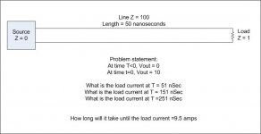
Do yourself a favor. Go to a nearby university, and ask an E/M prof to detail to you what happens when a short t-line, say 50 nanoseconds long, is fed by a zero impedance source, and the load is 1% of the line impedance.
Honestly, this is a trivially simple example that we were able to do the second week of E/M theory. The fact that you do not understand tells me that you did not take any E/M theory.
Your welcome. I believe it never was published because he tends to talk over the level of the target audience. There's a second part as well, I'll look for a link. I do not know where he stated the need to go up to 200 lumped LC's to closely model his lines.Still reading the Bateman stuff though..........
I'm sure there are other typo's as well. I recall scott (IIRC) pointed out an inversion in one of his equations, but do not remember if it's this one or another.On page 6:
"At audio frequencies, because R and G are dominant, not C or L, cable impedance is high but speaker system impedance in comparison is very low. "
Not true. Over most of the audio band R and C are dominant; only at the very lowest frequencies does G begin to dominate over C.
The typo's are a PITA, I'm sure there are still yet more in my recent article.
And yet, where R and G dominate, there is wave propagation...problem is the wavelength.Note that where R and G truly dominate you no longer have a transmission line but a distributed resistive ladder. Where R and C dominate (i.e. most of the audio range) you do not have wave propagation but diffusion - a distributed low pass filter (albeit with a rather high corner frequency, so the main effect is a little phase delay). Only when L and C dominate do you have wave propagation.
You too need to consult an expert in E/M at a university. Ask a prof to detail the model I point out to lucky.
Again, this is bog standard two weeks into the standard E/M course.
I love your subsequent hand waving dismissal, yet you've not understood bog standard t-line theory.
Seek the help of a good E/M prof...please.
Or, build the hardware and confirm what I've pointed out.
jn
I do not know where he stated the need to go up to 200 lumped LC's to closely model his lines.
"Many writers try to use quite small models, but to simulate to 10MHz, multiple stages are essential. I developed realistic Spice models using 201 frequency dependant four component nodes or stages, for each of my test cables."
(italics mine)
"Many writers try to use quite small models, but to simulate to 10MHz, multiple stages are essential. I developed realistic Spice models using 201 frequency dependant four component nodes or stages, for each of my test cables."
(italics mine)
Ah, I stand corrected...201...😱
Thanks.
Lucky, DF..
Neither of you intend on doing what I said to try, that much is obvious.
Here, take this to an E/M guy for the answers.
Another good alternate question. How many transits of the leading edge are required before the load current is 9.5 amps.
Extra credit: change the load from 1 to 100 ohms in steps, say 1, 2, 5, 10, 20, 50, and 100 (easy to plot log scale), and plot the time it takes for the load current to get to 9.5 amperes.(sorry, 95%)
Note that at 100 ohm load, the time to 9.5 amps (edit:95%) is exactly 50 nanoseconds, one transit. edit:whoops, the output voltage needs to be scaled to the load, sorry bout that. Alternatively, use a value of 95% of the final load current value..
Once the answer to the problem question is understood, think about this: The model neglects wire resistance, so to include that means that the line impedance will be higher, AND the prop velocity will go down. As such, the problem as outlined can only give the FASTEST the system can possibly respond to the step.
jn
Attachments
Last edited:
I can't seen to find Cyril's part two article, same name except part 2. Luckily, I have a paper copy of it.
In it, he details how to make a dual directional couple capable of viewing forward and reflected signals down to 3Khz. Good information, as well as verbage on his trials and tribulations in doing so.
Also, he does a lot on amp stability, and details a bit on using a zobel to tame the reflections especially at higher frequencies to prevent amp burst oscillation.
jn
OK since you ask........ the answer depends on the frequency or risetime of the event being driven by the source...... what happens when a short t-line, say 50 nanoseconds long, is fed by a zero impedance source, and the load is 1% of the line impedance.
For the case where R and G are negligible, as is here :
ZIN = Z0 [(ZL + Z0tan(k)) / (Z0 + ZL tan(k))]
ZIN is input impedance of the line seen by the driver
Z0 is characteristic impedance of the line
ZL is load/termination impedance
k is wavenumber length of the line
In this special case of audio where k ≈ 0 because the line is short yields
ZIN = ZL
Very simply, the driver sees the load impedance, the line is effectively invisible. In this case ZL= 0.01 Z0 as stated - simple as that, in parallel with lumped capacitance and in series with line inductance lumped.
This is easy to simulate, and to measure.
Last edited:
OK since you ask........ the answer depends on the frequency or risetime of the event being driven by the source.
Wrong. Try again. Guessing doesn't count.
Look at the jpeg I made, start over.
Use a 1 pSec rise time.
Then a 1 nSec risetime.
Then a 10 nSec risetime.
In all cases tell us how many transits are required to reach 95%.
Do it right.
Or, alternatively, find a prof in E/M theory, and ask..\
Eventually, one way or the other, you will hopefully figure out why the line has to magnetically charge.
I was prepped to ask you to examine the energy stored in the line inductance at 49.9 nSec, 149.9 nSec, 249.9 nSec, and final value, but you're not there yet.
jn
Last edited:
You need to understand the concept of wavenumber, and how small wavenumbers apply to propagation behaviour in elastic systems, such as TLs. All your examples, discussions equations fall apart because of this.Here, take this to an E/M guy for the answers.
You need to understand the concept of wavenumber, and how small wavenumbers apply to propagation behaviour in elastic systems, such as TLs. All your examples, discussions equations fall apart because of this.
Try again.
Please, go see an E/M expert, one who can answer the simple questions I posted.
This is a trivial problem, I am surprised you cannot do so. Well, then again, most people trip up when it comes to t-line understandings.
As the example shows, the load current for this extreme bandwidth question still takes ten plus microseconds to settle to within 5% of the final value, a concept you still do not understand.
Nor do you understand the concept of discerning the lumped element values for the given example, and calculating the LCR response. That'll get close the the same answer, you'll need more than one slice to get closer.
jn
Last edited:
These are not audioband risetimes, the wavenumber is not small so the line behaves as a TL no surprises.......you're missing the point.Look at the jpeg I made, start over.
Use a 1 pSec rise time.
Then a 1 nSec risetime.
Then a 10 nSec risetime.
My favorite letter to the editor was in IEEE Spectrum. It pointed out that the US power grid couldn't actually work as the half wavelength of a 60 hertz wave was 1,550 miles and the country is wider than this.
Yes the letter was really published.
Yes the letter was really published.
These are not audioband risetimes, the wavenumber is not small so the line behaves as a TL no surprises.......you're missing the point.
So, you ignore your previous statement that there is no way this type of construct can take more than 5 uSec, what did you call it...geological??
Quote:
Originally Posted by luckythedog :
5uS is half a geological era in this context, and for sure it should be readily observable on the line if present. But it isn't.
end of quote.
I use fast risetimes so that people like you might be able to understand the settling time concern.
Clearly, you did not get it. Please learn t-line theory before trying to discuss it.
Thanks,
jn
Last edited:
You need to use audioband risetimes - you'll reach a different and more realistic conclusion, there is no 5uS settle time for the cable and that's why its so tough to measure 🙄I use fast risetimes so that people like you might be able to understand the settling time concern.
My favorite letter to the editor was in IEEE Spectrum. It pointed out that the US power grid couldn't actually work as the half wavelength of a 60 hertz wave was 1,550 miles and the country is wider than this.
Yes the letter was really published.
If I remember correctly, it was brought up because local generation tended to NOT worry about wavelength because of their physical size. As such, the model for the system behavior was not consistent with the larger system's requirement.
It was only when the model was adjusted for the physical size of an interconnected continental system could power connections be considered at that scale.
Even now, they still struggle with load distribution and shedding, recall the northeast blackout caused by an overloaded and sagging set of powerlines?
jn
Last edited:
You need to use audioband risetimes - you'll reach a different and more realistic conclusion, there is no 5uS settle time for the cable and that's why its so tough to measure 🙄
Try again. It's been measured, it's not "tough".
Take the jpeg to a good E/M prof. Get back to us when you've understood the explanation.
Then we can go over the conversion from a pure t-line construct to it's equivalent LCR model, which produces the exact same result I've shown. edit: assume any permittivity you wish, the system is invariant to that.
Remember, the t-line result has been duplicated using an LCR model as well as actual test.
jn
Last edited:
Hmmm, I'm sure you said clearly the reason I couldn't observe this was because it is elusive in real cables........c'mon all this is good for a chuckle but it's nonsense, there is no 5uS latency/settle whatever between ends of the cable in audio. And yes, TLs are distributed LCR models no surprises there either. What you are observing in the current domain is effects of interactions between amp and load, where I do believe you will readily find your 5uS and then some.Try again. It's been measured, it's not "tough".
Take the jpeg to a good E/M prof. Get back to us when you've understood the explanation.
Then we can go over the conversion from a pure t-line construct to it's equivalent LCR model, which produces the exact same result I've shown. edit: assume any permittivity you wish, the system is invariant to that.
Remember, the t-line result has been duplicated using an LCR model as well.
jn
Is this t-line discussion just academic, or is this something that will break out into a practical example that actually has an audible effect on cabling?
I was following the thread out of morbid curiosity because most of it was funny, but the challenge of showing that image to a professor is very much something I can do. My wife works at the local college in the electronics / engineering department, and I'm in a position to actually talk to someone about it at the next cookout.
Will they teach me some nugget of knowledge that could potentially be applied to a system to improve signal transfer in speaker cable, or is it going to be "Eh, yeah, it exists, but there's not really **** anyone can do about it and you'll never hear it anyway."
- Status
- Not open for further replies.
- Home
- Member Areas
- The Lounge
- Speaker Cable lifters or stands?