When the power is applied the output of the inverter becomes active and the 360 is in approximately in parallel with the 91 so the output impedance approaches 75.
Add output Z of '04 logic gate (two gates in parallel) to 360R and you are still too far away from 75R for my taste.
It doesn't bother you that the '04 is a logic device and changes the pulse widths because the slice point is not well defined? It doesn't bother you that the signal levels are no longer on target?
I'm not propagating '04 chip, please don't mix me together with others who do this to save few $$.
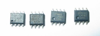
About CFA: have some of those 8-leg critters here. Not only from Analog, but also from National and Intersil. Picture is bellow.
All of them bought with my money, not through free sample program.
And about DMM: It is an internal joke, started HERE.
Attachments
Since I am a certified paranoid schizophrenic with OCD I don't mind spending a few extra dollars for an IC. Especially so since it will do precisely what I need it to.
As will the circuit I posted, apart from allaying your imaginary fears.😀
w
But I save money on resitors.😉 Those Caddock bulk foils are'nt cheap.😀As will the circuit I posted, apart from allaying your imaginary fears.😀
w
But I save money on resitors.😉 Those Caddock bulk foils are'nt cheap.😀
Ouch. Witty repartee.
w
Actually I do thank you for your input.Ouch. Witty repartee.
w
Your circuit almost certainly performs better than the one I copied, but there is a difference between engineering and over-engineering. If the OP is of the 'paranoid' school he will doubtless choose to spend the $7, if of a trusting nature he should have the option of saving $6. The jitter in this case is random, and in a comparatively recent study random jitter of 250nS proved inaudible to a panel of expert listeners.
I don't intend to open a debate about the audibility of jitter here, and you should not be discouraged from offering the products of your obvious expertise.
w
stormsonic is just pulling my leg about the impedances and the DMM.
I've been thinking about your 'over-engineering' comment and I disagree. I submit that my design is only adequately engineered. Over engineering would add auto equalization and auto gain control. BTW video Serial Digital Interfaces both std def and hi def include AGC and auto EQ. The BNC video connectors are true 75 ohm devices because all those little 'unimportant' errors add up and eventually come back to haunt you.
In broadcast video we use a lot of RS-422 for machine control. There is a company that makes RS-422 to RS-232 converters to interface a VTR to a PC using its COM port. The company took some of the kind of shortcuts proposed here. Their interface works under some conditions but not all so is that engineered properly or was it (IMO) shoddy work? I had my employer get rid of those crappy interfaces so that things work properly. There are enough problems in the world that we don't need to add more problems.
I'm one of the 'cleanup' engineers who has to figure out how the last guy screwed up and how to fix it so the problem goes permanently away. IMO any time you waste fixing something that shouldn't be a problem in the first place is just plain stupid. If a $7 chip ensures proper operation with no excuses, that's the only way to go. If you don't agree then you haven't had to fix enough of other engineers messes.
G²
you are finally getting the point I have been making all along.,............ Nevertheless, the impedances on the transmission line must be correct to keep VSWR at 1 and add no response 'bumps' an ringing.
The questioner asked for a splitter and you offered him an amplifier.
Even when prompted for a proper splitting solution you still offered an amplifier.
He needs a splitter. Once that splitting is achieved, then he decides whether he needs more gain.
you are finally getting the point I have been making all along.
The questioner asked for a splitter and you offered him an amplifier.
Even when prompted for a proper splitting solution you still offered an amplifier.
He needs a splitter. Once that splitting is achieved, then he decides whether he needs more gain.
And I told you why a simple splitter is not the correct solution for him. RF systems have AGC and a wide input range - easily a 1000:1. DACs do not. The level is supposed to be a a certain value. While many can tolerate a 'spread' of maybe +/- 6dB ( total spread of 4:1), it's not optimum. The distribution amplifier corrects this.
DACs and RF receivers is an apples vs oranges thing. They are not in any way the same.
G²
Last edited:
The BNC video connectors are true 75 ohm devices because all those little 'unimportant' errors add up and eventually come back to haunt you.
And therein lies the difference between SPDIF and video. SPDIF cables are specified with RCA connectors, BNC connectors would be overengineering, just as a video amplifier is overengineering in this context.
Engineering is about spending the right amount of money, not just putting in the highest performing device you can find, regardless of cost.
w
you are finally getting the point I have been making all along.
The questioner asked for a splitter and you offered him an amplifier.
Even when prompted for a proper splitting solution you still offered an amplifier.
He needs a splitter. Once that splitting is achieved, then he decides whether he needs more gain.
And I told you why a simple splitter is not the correct solution for him. RF systems have AGC and a wide input range - easily a 1000:1. DACs do not. The level is supposed to be a a certain value. While many can tolerate a 'spread' of maybe +/- 6dB ( total spread of 4:1), it's not optimum. The distribution amplifier corrects this.
DACs and RF receivers is an apples vs oranges thing. They are not in any way the same.
G²
He's right AndrewT, but for the wrong reason. It's not that RF systems have AGC, AGC doesn't impact on the sensitivity of receivers it's dependent on the receiver's noise figure, and DACs and RF receivers are the same in that they are sensitive to the SNR at the input. If you put in a splitter you halve the signal strength and you halve the slew rate but you do not lower the noise in the system.
Jitter vs. slew rate:-

The lower pic shows jitter vs. SNR for a sine wave zero crossing, but obviously square waves have a transition point too.

You can see the app. note these are taken from here:- http://pdfserv.maxim-ic.com/en/an/AN3631.pdf
For myself, however I think that concerns about random jitter are overstated, based on the conclusions of this 2004 study:- http://www.jstage.jst.go.jp/article/ast/26/1/50/_pdf
...which found an audibility threashold for random jitter of 250nS.
If anyone knows of any more recent studies, particularly ones that contradict this, I would be glad to know of them.
w
Exactly why I indicted in my first post that I did not want any attenuation.And I told you why a simple splitter is not the correct solution for him. RF systems have AGC and a wide input range - easily a 1000:1. DACs do not. The level is supposed to be a a certain value. While many can tolerate a 'spread' of maybe +/- 6dB ( total spread of 4:1), it's not optimum. The distribution amplifier corrects this.
Even though most consumer digital products use RCA cons. for SPDIF I believe it is spec'd to be a true 75ohm transmission line therefore worth the effort to use 75 ohm connectors throughout.Since I can purchase 75 ohm BNC connectors for less than I can RCA's I will go that route.And therein lies the difference between SPDIF and video. SPDIF cables are specified with RCA connectors, BNC connectors would be overengineering, just as a video amplifier is overengineering in this context.
Engineering is about spending the right amount of money, not just putting in the highest performing device you can find, regardless of cost.
w
Last edited:
I am aware of some of the jitter argument.
A normal line driver has a times2 amp driving the terminated line. The input to the line driving amp is almost equal to the output from the line. 1Vpp in becomes 1Vpp out near enough.
Now put in the splitter some way along the line.
A two way splitter will give half (1/2) the voltage at the two receive ends of the split ends.
The signal delivered to the receiver has been reduced by ~6dB, the noise has also been reduced by ~6dB.
Similarly a three way will deliver a ~-9.5dB signal to each of the three receivers and a 4way will deliver ~-12dB signal to each of the four receivers.
For all these split signals the noise from the source via the line driver amplifier is reduced exactly in proportion to the signal.
These lower level signals will be more susceptible to new noise being added after the split in the line. But that is the beauty of digital. It is very tolerant of noise. Jitter can be removed at any time by re-clocking the digital signal.
Before conversion to analogue the jitter must be within specification or brought within specification. reclocking would be an option for the DAC designer. But this is done as the last stage before the analogue conversion.
an acceptance ratio for lowest to highest digital input signal was quoted as 1:4. the straight through and all splits from 2Way upto 4Way all deliver a signal that falls in this 1:4 acceptable signal ratio.
If the attenuation of the signal is so great that the input signal at the DAC is out of specification then all that is needed is more gain. That original times2 line driving amplifier just gets a bit more gain to ensure the split signal is within the DAC receiving specification.
BTW,
the behringer DCX 24/96 accepts both spdif and aes signals (@ 110ohm) at it's input and specifies an acceptance ratio of 1:30
Last edited:
I am aware of some of the jitter argument.
an acceptance ratio for lowest to highest digital input signal was quoted as 1:4. the straight through and all splits from 2Way upto 4Way all deliver a signal that falls in this 1:4 acceptable signal ratio.
No, it doesn't. The target level is nominally 1V p-p. The unit should be able to tolerate +/- 6dB which puts the range .5 to 2 V p-p. If the source is properly at 1 V p-p and you drop it by 12 dB, you're down to .25 V p-p -- definitely in the bad zone. I'm as big a fan of passive splitting as the next guy but I also know that mis-terminating guarantees non flat response and low levels are a sure route to errors.
Oh, it's digital so it doesn't matter? It most certainly does because the response change causes ringing and if the ringing amplitude reaches the slice point where the receive system converts the analog representation of the digital signal to the operating logic levels the data may be corrupted. "The error correction will take care of it"? Nobody plans to run near the point where you have to RELY on the error correction because you may get a little further degradation and fall over the digital cliff where it no longer works. Look up pathological test signal.
My philosophy on this is - there are no big problems but a whole lot of little ones can sure look like a big one. Sorting them out is where the fun is.
G²
Stratus,
you are using the wrong arguments to try to convince me that I am offering bad advice.
I agree that splitting and ensuring correct termination is paramount to getting the best digiotal signal along the lines. You keep throwing in other distractions in the hope that you will bamboozle someone into simply adding an extra gain stage and to hell with the termination. You will never convince me that extra amplifiers can correct for miss-termination.
Your earlier post was starting to show sense but you have lost that by going down these dark alleys.
The signal delivered to the receiver has been reduced by ~6dB, the noise has also been reduced by ~6dB.
This is just wrong. The noise voltage in a system is related to the temperature, the resistance and the bandwidth. The noise figure of an attenuator is equal to its attenuation. This is why you have an LNA at the masthead or dish, and not at the (radio) receiver input. The cable is an attenuator, it attenuates the signal, but not the noise.
w
VRMS=sqrt(4kBTBR) where kB is Boltzmanns constant, T is in Kelvins, B is the bandwidth and R is the resistance. The noise power Pa = kBTB, i.e. it is unrelated to the resistance.
Last edited:
Could you refer me to a source that explains this in a form I can understand.The noise power Pa = kBTB, i.e. it is unrelated to the resistance.
Noise voltage, I can understand.
Insert an attenuator into a signal line. It cuts down the signal and it cuts down the noise, i.e. the attenuator, attenuates the signal+noise.
But what is noise power?
Stratus,
you are using the wrong arguments to try to convince me that I am offering bad advice.
I agree that splitting and ensuring correct termination is paramount to getting the best digital signal along the lines. You keep throwing in other distractions in the hope that you will bamboozle someone into simply adding an extra gain stage and to hell with the termination. You will never convince me that extra amplifiers can correct for miss-termination.
Your earlier post was starting to show sense but you have lost that by going down these dark alleys.
You keep insisting the DAC behaves like an RF device. With an RF carrier it's very important to get the correct modulation depth onto the carrier to properly recover the signal. Once it's on a carrier the levels can be ALL OVER the place because we have no way of knowing how far you'll be from a transmitter if by air or how much cable attenuation the signal will incur. Consequently the receive system has a very robust AGC system to correct the RF amplitude and then recover your signal. The key here is the modulation depth is very important. Still with me?
The SPDIF signal is not on a carrier. There is no AGC to fix up the gain. The level is important - same as the modulation signal in the RF systems.
The only thing the SPDIF signal and RF share in common is they have higher frequencies that require transmission lines and thus the need for proper termination to maintain flat response and consequently minimal ringing. Somewhere in the DAC interface is a comparator (a 1 bit A-D) which will determine where the edges of the signal are and convert it to the internal oprating level whether it's 5V or 3.3V or whatever the designer intended. Oversoots, ringing, reduced levels will disrupt this process. Some degradation is expected and can be dealt with but large level changes are inviting problems.
The BNC vs RCA is not a big deal for SPDIF as the frequencies involved are 'only' a few MHz. In my line of work we move std def and HD serial digital video signals that run 135 MHz and 750 MHz respectively. This puts more emphasis on proper transmission lines and connectors but the principles are the same. You can't have a lot of signal loss and still recover the signal. 12dB down is absolutely out of the question for these systems. Look up distribution amplifiers. If they weren't needed as you imply, why are there so many manufacturers making them?
The amplifier does not correct the termination nor is it intended to. The termination by definition inserts 6dB of loss on the signal. We correct this by boosting the signal 6dB before we send in on the next cable. The only things importnt on the DA is that IT terminates the input signal correctly so that the level is correct and there are no frequency response errors. The output sources the next cable with a new inline 75 ohm (cable impedance value) build out resistor so the process can be repeaed at the next destination whether it be another DA or the final signal use device. Analog DAs for professional use often have gain and EQ adjustments because transmission line inserts it's own losses. Serial Digital DAs include some AGC and auto EQ to correct for line losses. This is comaratively easy comared to analog as the signal has only ones and zeros so we know pretty well how the signal should be. Not so easy with analog. These are not distractions.
I'm sorry I'm not a better teacher.
G²
VRMS=sqrt(4kBTBR) where kB is Boltzmanns constant, T is in Kelvins, B is the bandwidth and R is the resistance. The noise power Pa = kBTB, i.e. it is unrelated to the resistance.
Could you refer me to a source that explains this in a form I can understand.
Noise voltage, I can understand.
Insert an attenuator into a signal line. It cuts down the signal and it cuts down the noise, i.e. the attenuator, attenuates the signal+noise.
But what is noise power?
It is not strictly true to say that an attenuator does not attenuate noise, however it internally generates noise at it's output which is equal to the noise absorbed. It is more correct to say that the Noise Figure of an attenuator is equal to its attenuation or loss, L, at 290 Kelvins. This applies to any passive device, switch, filter or splitter. The Noise Figure of a device is the noise factor expressed in decibels. The noise factor of a device is the input SNR/output SNR.
http://www.ittc.ku.edu/~jstiles/622/handouts/Noise%20Figure%20of%20Passive%20Devices.pdf
The noise voltage looking back into the 2 split lines is related to the 75R which the receiving device sees presuming you have designed your splitter correctly. The signal voltage is halved (for 6dB), consequently the SNR is halved.
Thinking about this in more intuitive terms, you could not reasonably expect to split the available signal power amongst a very large number of receivers. A single antenna will not drive an arbitrary number of receivers. You would expect to have a (low noise) distribution amplifier. The minimum detectable signal of a receiver is not related to it's gain it is related to it's Noise Figure or Noise Temperature. This is why the argument about AGC is fallacious.
Noise power is invariant with respect to resistance. Trivially if you expend a given amount of power in a resistor, then the larger the resistor, the greater the voltage across it and the smaller the current.
For a more comprehensive treatment see:- Digital and Analog Communication Systems - Leon W. Couch II, ISBN 0-13-571845-7, P429 - Thermal Noise Sources.
w
- Status
- Not open for further replies.
- Home
- Source & Line
- Digital Source
- SPDIF splitter