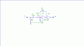
Reduce R18 to 1 K. Reducing it past that probably won't help much. Get rid of C12. Make sure that it is the HCU04 version.
Some guys say that it has a tendency to oscillate with no input......I never had problems. Bypass, bypass, bypass. Keeps leads short.......etc.
Jocko
Some guys say that it has a tendency to oscillate with no input......I never had problems. Bypass, bypass, bypass. Keeps leads short.......etc.
Jocko
Hi !
1st make sure that it is 74hc_U_04
The U stands for unbuffered. each inverter is just a komplimentary fet-pair. with R2 X5 is driven to his working point (yes it's analog !)
2nd the circuit should work fine 🙂
i use the same circuit without R18 and without C12.
Some people vary R18 between 0 - 10K, some people use a 10k resistor from output X5 to ground ...
telefunken use in his DA1000 a transformer with a transistor after instead.
There are many ways 🙂
Regards
Jobstens
Leave R18 in. The open-loop gain of an inverter is usually around 20 or so. Some may be a bit higher, but 50 is definitely the upper limit. Lowering it after a certain point buys nothing. Except:
Taking it out will lower the input Z. While 1K in parallel with 75R won't throw it off too much, 2K will lower it less.
Jocko
Taking it out will lower the input Z. While 1K in parallel with 75R won't throw it off too much, 2K will lower it less.
Jocko
thanks guys, i have played around with this circuit as described no joy. i was hoping that someone would offer a totaly new design
bob
bob
I've built this and it's stable...
http://www.diyaudio.com/forums/showthread.php?s=&threadid=54742
Warning though, it doesn't get full Jocko approval. 😉
I have no idea how much jitter the circuit adds - I'm thinking/hoping that hysteresis-induced phase noise is up in the MHz region, which a CS841x loop filter can eliminate and an AD189x ASRC can completely destroy. One of these days I'll feed the output of it back into the AP System Two and measure it.
Hi Gmarsh,
I built Elso's spdif input circuit with the ad8561 and it seems to work well. Have you compared yours to his circuit and how is it different/better?
Thanks,
300_baud
I built Elso's spdif input circuit with the ad8561 and it seems to work well. Have you compared yours to his circuit and how is it different/better?
Thanks,
300_baud
I don't know why you had trouble with it. An 'U04 inverter is only a pair of CMOSFETs tied together. It doesn't get much simpler. Did you use the right one...........i.e., unbuffered?
I have other circuits, but probably more than a noob wants to futz with.
Yes, Elso's circuit does work. But the diodes start to conduct, and that throws off the actual impedance that the signal sees.
We won't discuss hysteresis. Been done before. Although we would like to see if someone can measure its effect.
Jocko
hi Jocko,
Can you post some spdif input schematics that you would recommend even if they are more difficult to assemble? I wouldn't mind trying them out.
Thank,
300_baud
Can you post some spdif input schematics that you would recommend even if they are more difficult to assemble? I wouldn't mind trying them out.
Thank,
300_baud
yep im sure i tried the unbuffered types different manufactures too, the thing is very unstable (oscillation) when left open circuit, i want to have 5 of these stages on a pcb what i require is a circuit that works the complexity is not a problem as i am not what i would call a 'noob'
regards
bob
regards
bob
Jocko Homo said:
Yes, Elso's circuit does work. But the diodes start to conduct, and that throws off the actual impedance that the signal sees.
Jocko
How can the diodes start to conduct with a 0.5V p-p signal?
😕
The key word is "start". Doesn't take much to upset the impedance.
Plus all that stray whatever................
It has to look resistive.
Jocko
Plus all that stray whatever................
It has to look resistive.
Jocko
Maybe Jocko doesn't want to splain that again.....
.....so you may look here.... http://www.diyhifi.org/forums/viewtopic.php?p=5707#5707
300_baud said:hi Jocko,
Can you post some spdif input schematics that you would recommend even if they are more difficult to assemble? I wouldn't mind trying them out.
Thank,
300_baud
.....so you may look here.... http://www.diyhifi.org/forums/viewtopic.php?p=5707#5707
at the risk of repeating myself has anyone got a circuit that just works and that they will share
thanks
bob
thanks
bob
burbeck said:at the risk of repeating myself has anyone got a circuit that just works and that they will share
thanks
bob
A few posts back I read Elso's circuit works.
And I am sure Jocko's also.
http://www.diyhifi.org/forums/viewtopic.php?p=5707#5707

Attachments
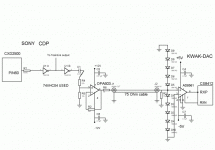
Hey guys.
I've built jocko's new circuit with the LMH6550MA chip and it works quite well. I've also built elso's spdif input comparator. but I've found that it's not as good. (sorry elso, no offense man)
I can't post the schematic now, because i'm in class at the moment learning SQL 🙂
When i do post the schematic, it didn't work with the 100 ohm resistors on the outputs of the LMH6550MA, so just don't use them.
but so far, i've concluded that jocko's circuit is better because:
1) it's more dynamic
2) the treble is way clearer (slight treble roll off with elso's)
3) more 3d like
4) more transparent
5) tighter and better defined bass
Yes, so basically jocko's circuit is a lot better.
I'm powering the circuit with dual supplies as opposed to a single supply and i'm guessing that it's much better. As a result, you don't need to power Vcm with Vcc/2 volts. (but according to the datasheet, you need to still bypass the pin)
On another note, I've also biased the LMH6550MA chip by installing two resistors in series. One end to Vcc and the other to ground and the midpoint being Vcm. Jocko also recommends that a filter cap be placed at Vcm pin to ground.
Anyways, it's worth the effort!
Take care,
300_baud
Here's the schematic as promised.. oh yeah i should also add that jocko's circuit is smoother, but more detailed as well when compared to elso's circuit.
Have fun guys 😉
btw, the transformer to get is a newava S22083 transformer, which you can get from digikey
Have fun guys 😉
btw, the transformer to get is a newava S22083 transformer, which you can get from digikey
Attachments
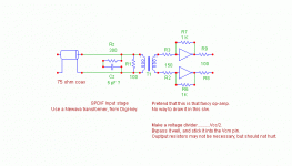
Since I haven't actually buit it.......
I am guessing that it may work better with Vcm biased up to 2.5 V even with dual supplies. That should allow DC coupling to the '841x RX chip.
But most guys will not have split supplies in their DACs, so running it on +5 only should work fine. Getting a nice linear circuit to work on only +5 V is tricky. I have used similar circuits made with discrete parts, and I am not crazy about how they act on +5V. You have to be careful that the input stage does not exhibit any compression, as that lowers the input impedance if the input starts to go into saturation.
Just like Elso's diodes.
BTW........there are ways around that...........and they have other benefits. But some other time for that.
Jocko
- Status
- Not open for further replies.
- Home
- Source & Line
- Digital Source
- spdif input circuit help