I have this amp that’s flickering between protection and power, I’ve remove the rectified rail volts and the power supply is ok. When the outputs ate removed it’s on but not going in protection, there is low side drive wave but not high side out of the chip IR2010S and I’m getting input on both drive pins on same IC..
Attachments

To get high-side drive, you generally have to supply the high-side B+ if there are no output FETs in the circuit. I use a 9v battery.
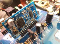
The high-side B+ has two terminals. Pin 6 is the negative terminal. Pin 7 is the positive terminal.
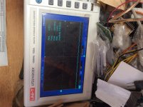
Connecting a load across the speaker terminals may be needed to see the drive signal.
Connecting a load across the speaker terminals may be needed to see the drive signal.
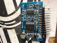
I failed to mention that during the boot up process the amp was drawing a lot of amp hence the protection. It didn’t draw current after removal of the output FETs, I reinsert two fets on both bank (one each) and I heard a little pop when I turn it on then the driver IC has exploded.
Attachments
The "Test" that Perry told you to do, had to be done without the mosfets.
I try to explain you better:
Usually drivers similar to yours use a voltage of 12v starting from a reference in the negative rail to generate the signal on the low side.
The high side always uses the same 12volt (isolated via a diode, called "VB DIODE") using a different reference (central point where your mosfets meet, so Source of the high mosfet and Drain of the low mosfet) which by convention we call "point H".
This way, when you turn on the amplifier, the low side is generated, creating a first pulse on the H point; this first impulse will become your reference for the high side, which will then generate its impulse; this is a loop that repeats itself indefinitely until class D works.
For this reason, if there are no mosfets installed, the high side will never come out, so Perry advised you to use a 9v battery to simulate that "pulse" you needed to see if the high side worked.
All these tests are done without mosfets.
If you installed new mosfets by doing this test, you caused more damage, damaging the good mosfets and probably the driver itself (if it wasn't already damaged before).
So now, you better replace everything (driver + mosfet + controls everywhere).
Do you have the polarity right on the high-side B+?
Yes I’ve double check before applying any voltages, the test was done without the FETs. It blows when the FETs was reinstalled.
The 4 FETs are still good, I’ve gotten the drive IC and I’m also going to change the 74C0 also.
Attachments
Are you saying that you did nothing but connect a 9v battery across the high-side B+ supply and it blew a hole in the IC?
No, I’m saying I didn’t get a drive signal from the chip with the 9v battery (FETs removed) but after I reinstalled the FETs and powered it back on then it blew.
I would have thought that the IC was defective if you didn't get a high-side drive with the 9v battery in the circuit.
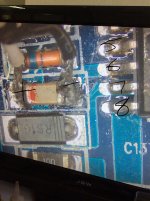
I’ve rebuilt the card for this amp, both IC were damaged but im still not getting a drive signal when I use the battery (8.85v) and in doing so the low side drive is struggling or died out while the battery is connected.
Also I went ahead an install the output fets, and two died, out of four and if memory correct it was the highside that have been shorted
Also I went ahead an install the output fets, and two died, out of four and if memory correct it was the highside that have been shorted
I’ve install the outputs in this amp and they shut down when I powered up the amp, when checked the output are shorted, what test can be done before I reinstall more output in the amp?
When using the 9v battery for generating the high side drive wave, what’s the ground reference point that must be used for the battery?
It appears that you had it right in post 9. Pin 6 is connected to the battery negative for a 16 pin IC.
- Home
- General Interest
- Car Audio
- SoundStream BXA1-5000D audio problem