Very strange, this scope seems to adjust it's reference 0 line by itself when switching buttons and vertical measurement.
I will take some more measurements and photo's. One moment.
I will take some more measurements and photo's. One moment.
Last edited:
So, what I did. I set my power supply to a steady 10.0v (measured with my multimeter)
I set the oscilloscope to 0.5V/div (probes 10x). Probed with both channels and adjusted to CAL potentiometer so both channels EXCACTLY had 2 divisions negative and 2 divisions positive.
It seems like this oscilliscope is extremely sensitive to exact the same voltage measurements on differential measurements. Otherwise it adjusts it own 0 level on the Y-axis (vertical).
Should be calibrated now 🙂
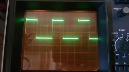
Ch1 on the Gate
Ch2 in the Source
0.2V/div (with CAL potentiometers calibrated)
2ųs/div (CAL potentiometer calibrated to exact 3 full waveforms, it's almost CC)
10x probes
DC-coupled
Differential measurement.
I set the oscilloscope to 0.5V/div (probes 10x). Probed with both channels and adjusted to CAL potentiometer so both channels EXCACTLY had 2 divisions negative and 2 divisions positive.
It seems like this oscilliscope is extremely sensitive to exact the same voltage measurements on differential measurements. Otherwise it adjusts it own 0 level on the Y-axis (vertical).
Should be calibrated now 🙂
Ch1 on the Gate
Ch2 in the Source
0.2V/div (with CAL potentiometers calibrated)
2ųs/div (CAL potentiometer calibrated to exact 3 full waveforms, it's almost CC)
10x probes
DC-coupled
Differential measurement.
Attachments
There is nothing wrong with that, that I can see.
If you probe it with only the ch1 probe, do you see the ripples, top and bottom, again?
If you probe it with only the ch1 probe, do you see the ripples, top and bottom, again?
As expected. It's due to a bad reference for the scope.
Try pin 2 (ch1) and 3 (ch2) of the optocouplers. The vertical amplifiers will have to be set to 0.1v, most likely.
Did you try with FETs in the circuit and with the limiter between the inductor?
Try pin 2 (ch1) and 3 (ch2) of the optocouplers. The vertical amplifiers will have to be set to 0.1v, most likely.
Did you try with FETs in the circuit and with the limiter between the inductor?
Previous time I tried one fet per bank, they all died instantly.
Should I measure the pins in differential measurements?
Ch2 attached to the Source?
Should I measure the pins in differential measurements?
Ch2 attached to the Source?
Does your multimeter read duty cycle?
Did you try with FETs in the circuit and with the limiter between the inductor?
I don't understand what you're referring to in #69.
Did you try with FETs in the circuit and with the limiter between the inductor?
I don't understand what you're referring to in #69.
Looks like my multimeter has a % sign on it yes.
I have just tried with one fet in the low-side bank.
No PWM measurable and a 13VDC on the speaker terminal
Should I try with 1 fet per bank (4 in total)
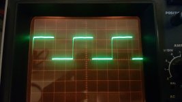
Attached first photo is from the LOW-side
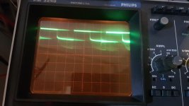
Attached second photo is from the HIGH-side
Ch1 on Pin2 and Ch2 on Pin3
50mV/div
2ųs/div
DC-coupling
10x probes
I have just tried with one fet in the low-side bank.
No PWM measurable and a 13VDC on the speaker terminal
Should I try with 1 fet per bank (4 in total)
Attached first photo is from the LOW-side
Attached second photo is from the HIGH-side
Ch1 on Pin2 and Ch2 on Pin3
50mV/div
2ųs/div
DC-coupling
10x probes
Attachments

Last edited:
Measure the duty cycle on the high and low side. One probe on the gate, the other on the source.
The waveform for the optocoupler should be on the reference line, like the other waveforms.
"I have just tried with one fet in the low-side bank."
What were you using as the limiter bridging between the board and the input of the inductor?
The waveform for the optocoupler should be on the reference line, like the other waveforms.
"I have just tried with one fet in the low-side bank."
What were you using as the limiter bridging between the board and the input of the inductor?
Duty cycle on the Low-side is 42.3%
Duty cycle in the High-side is 48.8%
As a limiter I'm using a 20ohm resistor per inductor.
The waveform is not in reference with the middle line.
With both measurements the oscilloscope was centered in the middle reference line before measuring.
Duty cycle in the High-side is 48.8%
As a limiter I'm using a 20ohm resistor per inductor.
The waveform is not in reference with the middle line.
With both measurements the oscilloscope was centered in the middle reference line before measuring.
You probably need a lower value limiter. I'd use a 2 ohm dummy load/12v current limiting resistor.
Did the FETs fail with the limiter in place.
Isn't pin 3 of each optocoupler grounded (0 ohms to the secondary CT)?
R72 on the driver board is in series with pin 2 of the optocoupler. Place probe 2 on pin 3 of the optocoupler and probe 1 on pin 2 of the driver board (which is on the other side of R72). Do you get a waveform that's sitting on the reference line?
The multimeter reads continuety between Pin3 of the optocoupler and secondary GND.
2ohm (100w) resistors soldered in place 🙂
Should I try all 4 banks loaded with a single fet?
Probe 2 on Pin3 optocoupler and probe 1 on Pin2 driver board (I assume you mean R70) will not result in being nicely referenced in the middle (on both sides of R70).
I measured the DC voltage with my multimeter (black probe on Pin3 optocoupler and red probe on Pin2 driver board) and it rode 2.12v
I think it should be OK for you to test one pair of banks (one high and one low). Just power up for a few seconds and check for heat in the FETs.
Twist the inductors to see if anything changes.
If the inductor did have a short, it could have been in the first turn of the terminal winding. That would have been broken when you desoldered and lifted it.
If the inductor did have a short, it could have been in the first turn of the terminal winding. That would have been broken when you desoldered and lifted it.
I have put some isolation under both outer transformer windings.
Powers up just fine, fets are happily switching and stay stone cold after 10min of idle.
Very strange, also the fact that previous fets were killed even without drawing excessive current.
I will order a bunch of new IRF640N to full the output section up.
When they are installed I will confirm if the amplifier is 100% working properly again.
Thank you very much for all the help on this amplifier so far 😀
As well as having learned how to measure in differential mode, I'm very grateful for it 😀
One reason that you may not have seen current draw is because there was sufficient current/energy from the charged caps to blow the FETs.
Test thoroughly and twist the inductors a few times during testing to confirm that they are no longer a problem.
You can use your scope normally without changing anything on your scope (compared to differential mode) by using only one probe. When you need differential mode, simply make sure that all settings for both channels are identical and use both probes.
- Home
- General Interest
- Car Audio
- SoundMagus X3500, Excursion HXA5K output PWM not working