Confirm that you read 0 ohms between the positive speaker terminal and the high-side FET source pads.
What do you see on the scope if you probe the high-side source pad?
What do you see on the scope if you probe the high-side source pad?
Confirm, High side source pads reads 0ohm with the positive speaker terminal.
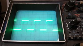
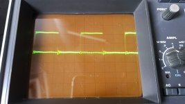
Attached is a photo from what is measured at the high-side source pads.
Oscilloscope is set at 10mV/div
This signal is not present at the speaker + terminal and seems to be filtered out by the output inductor.
Attached is a photo from what is measured at the high-side source pads.
Oscilloscope is set at 10mV/div
This signal is not present at the speaker + terminal and seems to be filtered out by the output inductor.
Attachments

Last edited:
Using your scope in differential mode, what's the signal across the gate and source of the high-side look like?
When posting scope images, both the vertical amplifier and the timebase are important.
When posting scope images, both the vertical amplifier and the timebase are important.
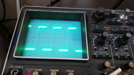
Main probe on the Gate
Differential probe on the source
0.2V/div
2ųs/div
Wobbly oscillation seems to be not present now.
A very clean PWM gate drive wave now.
Differential probe on the source
0.2V/div
2ųs/div
Wobbly oscillation seems to be not present now.
A very clean PWM gate drive wave now.
Attachments
Last edited:
That's a very low amplitude.
Are both channels of the scope set to DC coupling?
Both probes set to 10x?
Both vertical amplifiers set to 'cal' (full clockwise)?
Are both channels of the scope set to DC coupling?
Both probes set to 10x?
Both vertical amplifiers set to 'cal' (full clockwise)?
Sorry, forgot to say, probes are set to 10x
I use the differential probe, so only one channel is used (tektronix p2220)
Oscilloscope is set to AC coupling.
The 'cal' potentiometer was in the middle.
I will make a new photo with DC coupling and the potentiometer to full clockwise
I use the differential probe, so only one channel is used (tektronix p2220)
Oscilloscope is set to AC coupling.
The 'cal' potentiometer was in the middle.
I will make a new photo with DC coupling and the potentiometer to full clockwise
I see.... Yes, you are right. Watched the wrong video's.
I don't have a differential probe. Got a single Tektronix P2220 probe.
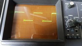
The photo is taken with the GND probe on the source and the main probe on the Gate. Removing the GND probe makes the gate drive wobbly again.
My old oscilloscope doesnt trigger at DC coupling, so I have to choose AC coupling when measuring waves (oscilloscope had it's best time, some buttons are not functional anymore)
0.2v/Div
2ųs/Div
I don't have a differential probe. Got a single Tektronix P2220 probe.
The photo is taken with the GND probe on the source and the main probe on the Gate. Removing the GND probe makes the gate drive wobbly again.
My old oscilloscope doesnt trigger at DC coupling, so I have to choose AC coupling when measuring waves (oscilloscope had it's best time, some buttons are not functional anymore)
0.2v/Div
2ųs/Div
Attachments
So, I bought a better working scope, with a couple extra probes. Here we go ^-^
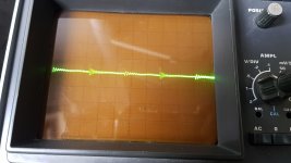
One probe on the Gate, another probe on the Source. Both on DC coupling.
0.5V/div
2ųs/div
Both probes on 10x
One probe on the Gate, another probe on the Source. Both on DC coupling.
0.5V/div
2ųs/div
Both probes on 10x
Attachments

Last edited:
Photo one is the drive signal to the Gate
Photo two is the signal on the Source
Photo three is both Gate and Source seperated and clear seenable
Photo four is both Gate and Source combined (DC coupled)
Photo two is the signal on the Source
Photo three is both Gate and Source seperated and clear seenable
Photo four is both Gate and Source combined (DC coupled)
The amplifier is instantly killing the output fets when I install one fet per bank. It doesn't pull excessive current.
There is a ticking sound, and the fet is shorted.
There is a ticking sound, and the fet is shorted.
Could that ticking be an intermittent short in an inductor that's arcing across?
Can you pull the input leg to the inductor and insert a limiting resistor, or even an incandescent lamp, to see if the problem is eliminated?
Can you pull the input leg to the inductor and insert a limiting resistor, or even an incandescent lamp, to see if the problem is eliminated?
Removed the 2 output inductors and replaced it with 2 current limiting resistors.
There was no ticking sound and both fets of the Hi-side (1 per bank) have survived.
There was no Gate drive and the fets were not driven.
Removing the fets made the gate drive appear again.
There was no ticking sound and both fets of the Hi-side (1 per bank) have survived.
There was no Gate drive and the fets were not driven.
Removing the fets made the gate drive appear again.
I don't know if there is a misunderstanding. What I wanted you to do it pull the input leg of the inductor and insert a limiter (resistor or lamp) to bridge between the pulled terminal of the inductor and the point on the board where the inductor leg was soldered. I didn't mean for you to replace the inductor with the limiter.
This would leave the circuit intact but would limit the current that could be drawn from the FETs.
This would leave the circuit intact but would limit the current that could be drawn from the FETs.
A misunderstanding. Thanks for your explaination.
I placed to resistors in series with the inductor now.
Installed one fet per bank on the Hi-side of the amp.
There is no PWM present on all 4 banks (Hi and Low side)
Gate measures 1.2v
Drain measures 70v
Source measures 1.2v
Speaker terminals measures 1.2v
Output fets are not killed.
I placed to resistors in series with the inductor now.
Installed one fet per bank on the Hi-side of the amp.
There is no PWM present on all 4 banks (Hi and Low side)
Gate measures 1.2v
Drain measures 70v
Source measures 1.2v
Speaker terminals measures 1.2v
Output fets are not killed.
- Home
- General Interest
- Car Audio
- SoundMagus X3500, Excursion HXA5K output PWM not working