Is there an output signal from into the 6-pin driver board?
I needed to clarify something that I didn't understand or see earlier. If (no FETs installed) you use either pin 4 of the driver board or the high-side source pad (same thing, correct?) as the reference, and measure the DC voltage on the 5v regulator on the driver board, what is the DC voltage on all 3 terminals?
I needed to clarify something that I didn't understand or see earlier. If (no FETs installed) you use either pin 4 of the driver board or the high-side source pad (same thing, correct?) as the reference, and measure the DC voltage on the 5v regulator on the driver board, what is the DC voltage on all 3 terminals?
I hope I understood your clarification correctly:
A little bit extra information as well.
WITH fets installed on only the High-side there is no PWM gate-drive on Pin6 (bank 1) and Pin5 of the optocoupler driver board on the High-side.
With fets installed on only the High-side there also is no PWM gate-drive on Pin5 (Bank 3) and Pin6 (Bank4) of the optocoupler driver board on the Low-side.
There seems to be no useable PWM drive coming out of the (master) 74HC00 driver board, just some strange distorted signals.
WITHOUT fets installed:
Correct, Pin4 and the source are connected and are the same
HIGH side driver board 5v regulator (78m05) measured to Pin4
Input pin: 11.11v
Output pin: 4.98v
GND pin: 0.00v
LOW side driver board 5v regulator (78m05) measured to Pin4
Input pin: 11.11v
Output pin: 4.96v
GND pin: 0.00v
With no FETs and the scope ground the secondary ground, do you see any signal on pin 2 of the driver boards (check high and low-side boards)? Pin 2 of the driver board goes to pin 2 of the optocoupler via a 330 ohm resistor (R70 on the photos I have).
Drive a signal into the amp if you don't initially see a signal.
Drive a signal into the amp if you don't initially see a signal.
To prevent a wrong measurement.
With secondary Ground, do you mean the GND from the optocoupler driver board?
Correct, Pin2 of the driver board is connected to Pin2 of the 6n137 optocoupler via a 330ohm resistor.
One of the 2 driver boards had a wrong 390ohm value when I first opened the amp (which should be the 330ohm).
Replaced it.
Secondary ground is generally the negative speaker terminal and the center tap of the secondary windings.
With no power applied, do you read 0 ohms between the secondary center tap and the negative speaker terminal?
With no power applied, do you read 0 ohms between the secondary center tap and the negative speaker terminal?
Confirmed. I read 0 ohm between the negative speaker terminal and the secondary center tap.
The negative speaker terminal is directly connected to the secondary center tap with a big decent cable.
On Pin2 of both 6n137 optocouplers is PWM oscillation present.
Measured with the GND reference of the negative speaker terminal.
20mV/div
The negative speaker terminal is directly connected to the secondary center tap with a big decent cable.
On Pin2 of both 6n137 optocouplers is PWM oscillation present.
Measured with the GND reference of the negative speaker terminal.
20mV/div
Attachments
Last edited:
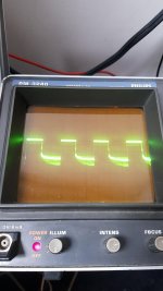
When posting waveforms, you need to post, vertical amplifier, timebase, note whether the scope was set to AC or DC coupling (DC is right virtually all of the time) and whether the probes are set to 1x or 10x. If you are going to post multiple photos with the same settings as before, you can just note that the settings are the same.
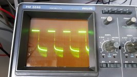
Photo 1 is the waveform of the Low-side 6n137 Pin2 referenced to secondary GND.
Photo 2 is the waveform of the High-side 6n137 Pin2 referenced to secondary GND.
10mV/div
2ųs/div
AC coupled (It does not show the waveform in DC coupling, it jumps out of the screen)
Probes on 10x
Photo 2 is the waveform of the High-side 6n137 Pin2 referenced to secondary GND.
10mV/div
2ųs/div
AC coupled (It does not show the waveform in DC coupling, it jumps out of the screen)
Probes on 10x
Attachments
Honestly, I'm not very familiar with differential mode measurements.
Most google articles and video's on youtube are with differential probes.
I think I understand the principle of the differential mode after seen an example with an OP-amp circuit.
As I think how I can measure in differential mode:
- The GND reference from the scope attach to a specific point in the circuit (for example the secondary GND or a (floating) rail voltage point in the amplifier)
- With channel 1 and channel 2 I can measure referenced to the specific point stated in the sentence above.
Is this correct? 🙂
A differential input uses two inputs to produce a single waveform. The simplest way to get a differential input is to use a differential probe. A differential probe has two signal leads and a mixer amplifier built into it. It feeds the scope a normal signal (a composite of the two signals input into the differential probe). The problem with differential probes is that they're expensive.
The alternative is to use two scope probes and and both inputs of your oscilloscope. This is how you have to set up your scope:
Two probes
Both scope inputs used
Input set to add
Both channels set to DC coupling
Both vertical amps set to the same voltage
Ch2 input set to invert
Bandwidth limited (works best for most measurements in car amps)
Trace aligned to the reference line on the scope's display
Ground leads for both probes connected together (not always necessary)
After setting up the scope, you need to confirm that it's working as it should. With the vertical amp set to 5v/div, touching the probe that's connected to Ch1 to the positive terminal of your 12v power supply should make the trace deflect about 2.5 divisions up from the reference (like it always does, seen below). Doing the same with the probe connected to Ch2 should make the trace deflect down about 2.5 divisions. Touching both probes to the positive terminal of the 12v power supply should cause no deflection. If it does, something isn't right.
I know that this may not be as simple as the isolated scope but if you take the time to learn it one time (even if it takes an hour or more of your time), you have that knowledge and this tool to use for the rest of the time you need to use a scope. Using the analog scope will give you much larger and cleaner waveforms.
It works, absolutely fantastic 😀
Thank you so much for the detailed explaination!!
It is highly appreciated 🙂
Since the maximum vertical value from my oscilloscope is 2V/div, I have put it on 1V/div and both probes to 10x.
Measuring the 12v power supply with Ch1 gave me a positive 1.2 divisions from the middle reference line, measuring with Ch2 gave me a negative 1.2 divisions from the middle reference line.
Both probes on the 12v supply gave no results.
So, confirmed the setup is working.
What would you like me to measure? (I'm so hyped to try this feature 😀)
First, measure the low-side drive. Remember, ch2 probe on the source. Post a photo of the drive.
You need to use DC coupling (possible in differential mode).
You need to use DC coupling (possible in differential mode).
Would you like me to measure the input drive of the Optocoupler board, Pin2 from the optocoupler or the gate drive?
Let's start with this.
Set the timebase and vertical amplifier so that you get about 3 full cycles and the waveform fills approximately 3/4 of the top half of the display.
Set the timebase and vertical amplifier so that you get about 3 full cycles and the waveform fills approximately 3/4 of the top half of the display.
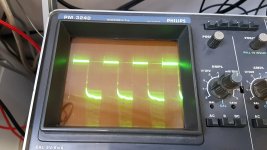
So, I measured the low-side gate drive here
Ch2 attached to Pin4 (source) of the driver board.
Ch1 attached to the gate resitor
I needed to press the HF button (below the TIME/DIV potentiometer) in order to trigger the scope at DC-coupling (first the DC button was pressed). Otherwise the scope could not be triggered in DC-coupling.
0.2V/DIV
1ųs/DIV
Probes on 10x
It was not possible to set the vertical measurement to a larger amplitude. Otherwise the scope does not trigger and makes it a straight DC line.
Attachments
Last edited:
The photo in #56 wasn't there previously.
Did you align the trace to the reference line before probing those points?
The trace should not be below the reference line.
Are both channels set to DC coupling?
If the differential setup is working, when probing the low-side gate with the ch1 probe alone, the trace should disappear down. Then when touching the ch2 probe to the source leg, the waveform should show up as a normal waveform.
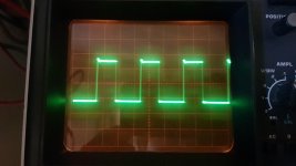
Yes, the line was centered in the middle.
Both probes set to DC-coupling
When measuring the gate-drive with Ch1 with 2V/div set I see a negative drive at about -70v (doesn't trigger, I see 2 lines), about 3.5 divisions negative, almost jumps out of the screen.
When measuring the gate-drive with Ch2 with 2V/div set I see a positive drive at about +70v (doesn't trigger, I see 2 lines), about 3.5 divisions positive, almost jumps out of the screen.
When I measure the gate-drive with Ch1 to the Gate and Ch2 to the source, it happens as you stated, with 2V/div.
Both probes on the same gate resistor has no measurable results.
Last edited:
- Home
- General Interest
- Car Audio
- SoundMagus X3500, Excursion HXA5K output PWM not working