Hi All.
Looking for your advice.
I learned that the principal partners at Cerwin Vega had a falling, and, after departing, one of them formed SoundDynamics.
I have a pair of SoundDynamics 2 Way Loudspeakers.
Largish cabinets which feature 10" Woofers and 1" Tweeters fitted with wave guides.
They are very satisfying when it comes to bass reproduction but lack in treble area. Compared to other Speakers I own they are quite flat in the higher frequencies.
I ripped out one of the crossovers this weekend and list the parts as follows:
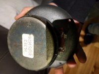
Resister: Cheap sandcast example marked with the values 7 watt, 2 ohm.
Capacitors: One Intercap 4.7mfd 250v & a smaller Intercap 4.7mfd 100v.
Inductor: Air core, thin copper winding, 35mm diam, 15mm centre hole, & 7 mm high. Scratching the red finished wire winding revealed a shiny copper color.
What do you recommend in terms of upgrading the crossovers?
cheers
Cliff
Looking for your advice.
I learned that the principal partners at Cerwin Vega had a falling, and, after departing, one of them formed SoundDynamics.
I have a pair of SoundDynamics 2 Way Loudspeakers.
Largish cabinets which feature 10" Woofers and 1" Tweeters fitted with wave guides.
They are very satisfying when it comes to bass reproduction but lack in treble area. Compared to other Speakers I own they are quite flat in the higher frequencies.
I ripped out one of the crossovers this weekend and list the parts as follows:
Resister: Cheap sandcast example marked with the values 7 watt, 2 ohm.
Capacitors: One Intercap 4.7mfd 250v & a smaller Intercap 4.7mfd 100v.
Inductor: Air core, thin copper winding, 35mm diam, 15mm centre hole, & 7 mm high. Scratching the red finished wire winding revealed a shiny copper color.
What do you recommend in terms of upgrading the crossovers?
cheers
Cliff
Last edited:
One place to start would be to measure them and adjust the values, although there are many other things you can do to improve a given speaker. What kind of things would you be prepared to do?
I recommend that you give us enough info to go on - what model are the speakers?
are the caps electrolytic or otherwise? What is the crossover schematic?
If the caps are electrolytic, probably best to replace them with MKT or something similar;
if the resistor is padding the tweeter, for more treble reduce its value
are the caps electrolytic or otherwise? What is the crossover schematic?
If the caps are electrolytic, probably best to replace them with MKT or something similar;
if the resistor is padding the tweeter, for more treble reduce its value
I recommend that you give us enough info to go on - what model are the speakers?
are the caps electrolytic or otherwise? What is the crossover schematic?
If the caps are electrolytic, probably best to replace them with MKT or something similar;
if the resistor is padding the tweeter, for more treble reduce its value
Thanks Peter
They are 2 way Soundynamics Loudspeakers.
Enclosure: 700 mm high, 360 mm wide, 310 mm deep.
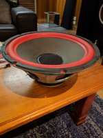
The 10" drivers aren't marked.
They appear to be original.
The diaphragms have been refoamed recently.
See photos.
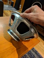
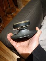
The 1" dome tweeters are marked: PLZ EL 4DR 5162.
They wave guides marked Model NO HL-C-01SD
The Intercap 4.7mfd 110v caps feeds the tweeters
The Intercap 4.7mfd 250v caps feed the woofers.
I believe they are electrolytic, but find examples online to verify.
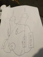
See crossover diagram in photos.
What are your thoughts?
Attachments

Last edited:
'The Intercap 4.7mfd 110v caps feeds the tweeters The Intercap 4.7mfd 250v caps feed the woofers.' - if the schematic provided is correct, there is no crossover on the woofer, & 3rd order on the tweeter.
After replacing any electrolytics, try shorting out the resistor & see how that affects the treble. If too much, then replace the resistor with something in between 0 & 2 ohms, try 1 ohm to start.
After replacing any electrolytics, try shorting out the resistor & see how that affects the treble. If too much, then replace the resistor with something in between 0 & 2 ohms, try 1 ohm to start.
Thanks Peter
The Intercap 4.7mfd 110v caps feeds the tweeters
The Intercap 4.7mfd 250v caps feed the woofers.
I believe they are electrolytic, but find examples online to verify.
See crossover diagram in photos.
What are your thoughts?
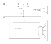
No offence ... but I think you've traced that crossover incorrectly...
Most likely the tweeter cap and resistor are in series with the tweeter. The coil is in series with the woofer and it's cap is actually shunting to ground. This would make the most sense.
Around here the Sound Dynamics were considered mass-market boxes and they respond fairly well to tweaks.
1/ brace the box
2/ solder in better wire
3/ swap out the aged, cheap caps for decent polys (alredy mentioned)
4/ ductseal or similar on the back of the waveguide
5/ puzzlekoat the woofer cone — this will smooth the response, aid in the roll-off up top, reduce the cone self-noise
A bit more invasive.
6/take the lip that is around the edge, round over or chamfer is even better. Since this is often what holds th egrill in pace you will either lose it or figure another way to afix it.
I have probably miss some.
dave
What Dave said... ignore my advice on resistor change, I thought it was in series with the tweeter
Thanks Dave.
I was planning to also line the boxes to eliminate resonance.
Any particular area within the boxes?
Apart from the electrical components, the wiring includes the speaker terminals, and driver wiring.
Driver wiring and female spades appear pretty healthy (thickness/copper).
I can junk the speaker terminals for something better, but what wiring would you replace with?
Any Caps you recommend without going overboard?
Is mastic sealant suitable?
Does Modpodge leave a gloss appearance?
How many coats do you recommend?
Are you referring to the waveguide?
While at it, should I junk the sandcast resistors for a quality replacements with the same value?
Also, when soldering crossovers, should certain solders be used or avoided?
thanks heaps.
Looking forward to implementing the tweeks. 🙂
I was planning to also line the boxes to eliminate resonance.
1/ brace the box dave
Any particular area within the boxes?
2/ solder in better wire dave
Apart from the electrical components, the wiring includes the speaker terminals, and driver wiring.
Driver wiring and female spades appear pretty healthy (thickness/copper).
I can junk the speaker terminals for something better, but what wiring would you replace with?
The market is so diverse, I think it could be easy to either overspend or buy poor quality!3/ swap out the aged, cheap caps for decent polys (already mentioned) dave
Any Caps you recommend without going overboard?
4/ ductseal or similar on the back of the waveguide. dave
Is mastic sealant suitable?
5/ puzzlekoat the woofer cone — this will smooth the response, aid in the roll-off up top, reduce the cone self-noise dave
Does Modpodge leave a gloss appearance?
How many coats do you recommend?
6/take the lip that is around the edge, round over or chamfer is even better. Since this is often what holds the egrill in pace you will either lose it or figure another way to afix it.
dave
Are you referring to the waveguide?
While at it, should I junk the sandcast resistors for a quality replacements with the same value?
Also, when soldering crossovers, should certain solders be used or avoided?
thanks heaps.
Looking forward to implementing the tweeks. 🙂
Last edited:
I was planning to also line the boxes to eliminate resonance.
That is definitly a good idea. Are they sealed or vented?
Any particular area within the boxes?
Given that you are working thru the driver hole, i would run some (say 18mm x 40mm) strips up the sides and across the top and bottom with a cross piece tieing the sides together and one running up the back. Plywood or hardwood. MDF is not stiff enuff, but sometimes all that is available.
Driver wiring and female spades appear pretty healthy (thickness/copper).
I can junk the speaker terminals for something better, but what wiring would you replace with?
The spades should go. For the tweeter i would use solid core wires pulled from a CAT5/6 (in wall) cable, for the woofer i would also try one and if i find that the bass gets too fat, use multiples.
Any Caps you recommend without going overboard?
We usually use the cheap Solens, but i believ MKP have been suggested and teh caps from Brian Cherry at diy Hifi Supply (?) in Hong Kong are good. But i would suggest that almost any poly cap will be better than the else, even if it hadn’t expired because of age.
Is mastic sealant suitable?… Are you referring to the waveguide?
Yes. Yes.
Does Modpodge leave a gloss appearance?
How many coats do you recommend?
You can get gloss or flat. I use the gloss but have both. You can even get it with sparkles init (not recommended).
I am usually doing FR so i use as little as i can get away with. Woofers can support more, but you should proceed slowly as it will affect the extension at the top, too much and that big woofer might already have issues reaching to the tweeter. The ModPodge needs to be thinned a tiny bit, given that what comes out of th ejar is variable, it is hard to give a receipe. With a woofer not as critical, but not enuff thinning is better than too much.
This may be helpful: Speaker Tweeks -- Puzzlecoat & Ductseal
While at it, should I junk the sandcast resistors for a quality replacements with the same value?
You can definitly get a better R, but it won’t make near the difference as the caps.
Also, when soldering crossovers, should certain solders be used or avoided?
I have so much archived old-style lead solder i have not experiemnted.
These speakers will never be crazy good (but could be crazy enjoyable) so don’t go over the top. Save that for your quality diy build. You will learn alot with the tweaks, and you might want to be patient enuff to go slow and listen to what each step does (i have done that so many times, i no longer have the patience :^)
dave
Hi Dave.
Thanks for your guidance.
The boxes are vented.
There are existing 25mm x 16mm x 85mm, 4 bracing the sides to the front around the woofer, and also one on each rear bracing the sides to the back.
There is also a 16mm x 50mm piece bracing the front panel to the rear panel next to the tweeter. All mdf I'm afraid.
I'll fit extensive bracing as well as fitting sound insulation.
Does the copper age?
If so, what type/material spades will I replace them with?
Not familiar with cat5/6 wire.
What gauge solid core wire will I choose?
I'll replace the Caps with identical mfd values.
But what voltage should I choose?
Existing caps are 1 @ 250V & 1 @ 100v
Should I also replace the air core copper coil?
According to your diag existing is xxMH
The coil is of thin copper winding, 35mm diam, 15mm centre hole, & 7 mm high.
Scratching the red finished wire winding reveals a shiny copper color.
What value/spec should I select?
Sorry for the persistence.
After all, it's all in the detail.
cheers
Cliff 🙂
Thanks for your guidance.
That is definitly a good idea (insulation). Are they sealed or vented? dave
The boxes are vented.
Given that you are working thru the driver hole, i would run some (say 18mm x 40mm) strips up the sides and across the top and bottom with a cross piece tieing the sides together and one running up the back. Plywood or hardwood. MDF is not stiff enuff, but sometimes all that is available. dave
There are existing 25mm x 16mm x 85mm, 4 bracing the sides to the front around the woofer, and also one on each rear bracing the sides to the back.
There is also a 16mm x 50mm piece bracing the front panel to the rear panel next to the tweeter. All mdf I'm afraid.
I'll fit extensive bracing as well as fitting sound insulation.
Why junk the spades?The spades should go. For the tweeter i would use solid core wires pulled from a CAT5/6 (in wall) cable, for the woofer i would also try one and if i find that the bass gets too fat, use multiples.
dave
Does the copper age?
If so, what type/material spades will I replace them with?
Not familiar with cat5/6 wire.
What gauge solid core wire will I choose?
We usually use the cheap Solens, but i believ MKP have been suggested and teh caps from Brian Cherry at diy Hifi Supply (?) in Hong Kong are good. But i would suggest that almost any poly cap will be better than the else, even if it hadn’t expired because of age.
dave
I'll replace the Caps with identical mfd values.
But what voltage should I choose?
Existing caps are 1 @ 250V & 1 @ 100v
Should I also replace the air core copper coil?
According to your diag existing is xxMH
The coil is of thin copper winding, 35mm diam, 15mm centre hole, & 7 mm high.
Scratching the red finished wire winding reveals a shiny copper color.
What value/spec should I select?
Sorry for the persistence.
After all, it's all in the detail.
cheers
Cliff 🙂
Last edited:
The boxes are vented
Then you want to just line the box. Not too much or the tuning changes.
T
here are existing 25mm x 16mm x 85mm, 4 bracing the sides to the front around the woofer, and also one on each rear bracing the sides to the back.
There is also a 16mm x 50mm piece bracing the front panel to the rear panel next to the tweeter.
Sides to the front and back to the sides, are corner blocks? If so they provide little bracing, they have a different purpose. The one from the baffle to the back is a good start.
Why junk the spades?
Spades make manufacturing easy, but add an extra connections interface and one that can age.
If so, what type/material spades will I replace them with?
Solder the wire to the terminals.
Not familiar with cat5/6 wire.
What gauge solid core wire will I choose?
It is network cable for ethernet. It is made of 4 twisted pairs of wire. The stuff you want is for in wall installation and the strands are 24g solid copper with PVC or teflon insulation. The latter is harder to find, but better.
I pull the pairs apart and use a single pair. Most of the speakers we do are FR. For woofers that want some current i will use multiple pairs.
It is cheap* & good, it appeals to the Frugal-Phile™ in me.
*(often free scraps can be had from computer shops)
But what voltage should I choose?
100V (or even less) is enuff, but it is often difficult to find the good stuff that small. ometimes i end up using 450 or even 600V because that is all i can find. Those V values ar eintended for tube amplifiers.
Should I also replace the air core copper coil?
No. The nature of the XO suggests that the inherent Rs are used as part of the XO so a different coil would screw that up.
ssmH means we don’t know the value, it would have to be measured — they rarely come labeled with values.
dave
Then you want to just line the box. Not too much or the tuning changes. dave
Does this mean no bracing, or continue with plywood or hardwood as advised?
I was planning to use the "melamine magic sponges" for internal insulation.
The members are recommending it.
Comes in 20 mm thick blocks (100 mm x 60 mm)
Can be fitted against each other & fastened with hot glue stick.
Is this OK?
Solder the wire to the terminals. dave
What do you recommend regarding Binding Post/Crossover Terminals?
Existing is iron.
I'd like to remove anything magnetic from the path.
It is network cable for ethernet. It is made of 4 twisted pairs of wire. The stuff you want is for in wall installation and the strands are 24g solid copper with PVC or teflon insulation. The latter is harder to find, but better.
I pull the pairs apart and use a single pair. Most of the speakers we do are FR. For woofers that want some current i will use multiple pairs. dave
What does FR mean?
I have some CAM OFC Shielded multi strand Audio Cable.
Inside blue cover is:
red and yellow jacketed wires (7 strand)
red and white jacketed wires (7 strand)
Each pair is shielded in foil jackets
&
bare copper wire & black jacketed silver colored wires (7 strand) with no foil jacket.
Can I utilise these for my crossover and driver wiring?
Wires seem quite thin.
By comparison, existing crossover to driver cabling is much thicker.
I would have thought the thicker the better??
100V (or even less) is enuff, but it is often difficult to find the good stuff that small. Sometimes i end up using 450 or even 600V because that is all i can find. Those V values are intended for tube amplifiers.
dave
Tube amplifiers won't be an issue.
I was hoping to understand thinking behind Cap Voltage decisions.
The aim being sound quality/value/electrical requirement.
Can you help me to understand the thinking behind Cap Voltage decisions?
For example, is it by accident or by design that existing Caps are 100v & 250v?
many thanks.
C
Last edited:
FR stands for full-range.
Some have suggested that higher Voltage capacitors equates to better sound. Some have not managed to find such a difference.
Some have suggested that higher Voltage capacitors equates to better sound. Some have not managed to find such a difference.
Does this mean no bracing, or continue with plywood or hardwood as advised?
Braces are a different matter than the way the damping is done. Brace then damp the walls.
I was planning to use the "melamine magic sponges" for internal insulation.
I don’t know about that. I’d still advise a natural material felt like cotton or wool.
What do you recommend regarding Binding Post/Crossover Terminals?
My personal experience, would have me looking for 5-way binding posts with little metal in them, industry standard 3/4” spacing and be removalable (a cup or plate). I like the posts not sticking out, as if the do it becomes all to easy to break them off accidentally.
Avoid any with tones of metal. Cheap looking plastic nutted posts work better, and given the loudspeaker being tweaked are totally;y appropriate. I also like the smaller ones that put as small a whole as possible so as to cause minimal weaking of the panel. In your case, whatever is already there could drive things.
Existing is iron.
I'd like to remove anything magnetic from the path.
I have some CAM OFC Shielded multi strand Audio Cable.
I prefer solid core, and don’t gotoo thick. Been there done that, have a tote full of 10-14g stranded some turning green.
But try what you have (you’ll be happy if the binding posts are removable if you decide to change it. No point in going over the top with these.
Wires seem quite thin.
You have to keep in mind that males tend to have a “mine is bigger than yours” and you often see this in people’s choice of speaker wire. You have to ask how much current are the speakers going to draw. Efficient speakers (these should be fairly high) draw less current, higher impedance speakers draw less current, as long as the phase angles do not get large.
I was hoping to understand thinking behind Cap Voltage decisions.
The caps in a loudspeaker rarely see or need high voltages unless grossly inefficient. 50V is usually more than sufficient, but it is hard to find them that small (in poly caps). Given the XO in these, the caps only affect the top 2 or 3 octaves, almost the entire sound will be coming from the woofer.
For example, is it by accident or by design that existing Caps are 100v & 250v?
It is what they could buy in BIG quantities cheap. The 1st one takes a lot of the lower frequency stuff out of the signal so that the 2nd one does not see as much. These speakers were often played REALLY loud and often abused, and it is way cheaper to spend a few extra pennies on a cap than having to replace it in the field.
By abused i mostly mean too small an amplifier pushed into heavy clipping, a receipe for melting things.
dave
Braces are a different matter than the way the damping is done. Brace then damp the walls.
The caps in a loudspeaker rarely see or need high voltages unless grossly inefficient. 50V is usually more than sufficient, but it is hard to find them that small (in poly caps). Given the XO in these, the caps only affect the top 2 or 3 octaves, almost the entire sound will be coming from the woofer.
dave
Hi Dave.
You're correct that Loudspeaker manufacturers are focused in reducing their costs.
While engaged in bracing the boxes I noticed the fitted ports were stamped "4" ABS Sewer". ��
I began by bracing the cabinets with strips of hardwood (40mm x 18mm).
Along both side panels as well as top & bottom panels, and a strip between front & back panels.
These were glued and screwed into place.
The longer strips needed to be screwed/glued together once placed inside the cabinets via the woofer holes to form the correct lengths.
I have painted one coat of Mod Podge (matte) on the woofer cones so far.
Another coat to come in 24 hours.
Only the rear of the cabinets had insulation fitted.
I need to source wadding for all the bare interior surfaces.
I'm working on ordering crossover and non ferrous binding post replacements.
Top of the list (locality and price) are:
4 x Jantzen 4.7uF MKP Polypropylene Standard Z-Caps &
2 x Jantzen 2 Ω Superes 10 Watt Wire Wound, Ultra low-inductance resistors.
Is this brand OK?
The next level up results of multiple times more price wise.
Last edited:
...ABS Sewer
Excellent for ducted vents. Much cheaper (and better IMO) than the store bought ones.
and non ferrous binding post replacements.
Be wary of teh all metal ones. They ar eusually pricier and inferirior to plastic nuted ones.
4 x Jantzen 4.7uF MKP Polypropylene Standard Z-Caps &
2 x Jantzen 2 Ω Superes 10 Watt Wire Wound, Ultra low-inductance resistors.
Is this brand OK?
I might look at those for an expensive speaker, but probably be overkill here. Do but the cheapest you can from them.
dave
I might look at those for an expensive speaker, but probably be overkill here. Do but the cheapest you can from them.
dave
Thanks Dave
While I have time due to my search for the binding posts, I'll see if I can save a little more on the crossover electronics.
For the 4 x Jantzen 4.7uF MKP Polypropylene Standard Z-Caps &
2 x Jantzen 2 Ω Superes 10 Watt Wire Wound Resistors the damage is around AUD$50.
A Loudspeaker enthusiast is recommending stuffing the cabinet with fibreglass insulation for damping. It was indicated to fill the enclosure by cramming it with the fibreglass batt material.
Any thoughts?
Cheers
Last edited:
- Home
- Loudspeakers
- Multi-Way
- SoundDynamics Loudspeaker Crossover upgrade??