I have a 1 ohm 10 watt resistor and a 10 ohm 1 watt resistor, should u used a 2 ohm 1 watt resistor to test it or will either do?
Use the 1 ohm 10w but only power the amp up for a few seconds and then check the resistor to see if it's getting hot.
To be safe, could i tap into the primary windings of a working amplifier? I have plenty amplifiers laying around.
Ok, i tried as you stated Perry. The 1 ohm 10 watt resistor did not get hot, the transformer barely got warm after 1 minute.
Could i check the voltage on the secondary windings? If so, (with black led on the center if the secondary windings and red on the outer windings I'm only getting 2 mv to 14 mv from the secondary windings. I'm i getting these readings because i don't have rectifiers on the secondary windings?
Could i check the voltage on the secondary windings? If so, (with black led on the center if the secondary windings and red on the outer windings I'm only getting 2 mv to 14 mv from the secondary windings. I'm i getting these readings because i don't have rectifiers on the secondary windings?
I measured the current on the center windings and it was 4mA. So its not pulling excessive current.
Connect the ground for your scope to the center leg of the secondary (careful not to let the ground clip short to the other windings). Do you see a good square wave on the 4 outer terminals of the secondary of the small transformer?
I'll solder jumpers to the secondary pins that way nothing gets shorted, a little more work but i don't mind it. I'll post results later tonight (hopefully, lol, if not ...first thing in the morning.)
I checked it and i have no waveforms. I even checked the frequency with my fluke 111 and itwas 00.0hz with 2 mv.
I think this transformer is bad. But i would hate to order one @ 45.00 and to find out its was okay and that the transformer was not the problem.
I think this transformer is bad. But i would hate to order one @ 45.00 and to find out its was okay and that the transformer was not the problem.
Check for continuity between the primary pins. You should find continuity between 3 of them.
Do the same for the secondary. There should be continuity between all 5.
You still have the option of adding windings to the main transformers.
Do the same for the secondary. There should be continuity between all 5.
You still have the option of adding windings to the main transformers.
Yes i have continuity between all three primary windings and same for the secondary windings.
I wish i knew how to do add the extra windings on one of the main transformers. I know i have to use magnet enamel copper wire (16g to 20g)? But then would i add rectifiers/fusible resistors? Or just send the windings straight to where the secondary windings where on the board?
I wish i knew how to do add the extra windings on one of the main transformers. I know i have to use magnet enamel copper wire (16g to 20g)? But then would i add rectifiers/fusible resistors? Or just send the windings straight to where the secondary windings where on the board?
You don't need anything larger than 20g. Start with 5+5 windings. You will connect the center-tap from those 10 windings to the center tap of the secondary for the small transformer. The two other windings will go into the two points where the ±15v output from the small transformer were connected.
When you state that you had continuity, did you essentially read 0 ohms for all windings?
When you state that you had continuity, did you essentially read 0 ohms for all windings?
When you state that you had continuity, did you
essentially read 0 ohms for all windings?
Yes, my meter read 0.2ohms due to the leads having a .2 ohm resistance.
Is there any good sites where i can learn more on how to wind a transformer, I've never done it but don't get me wrong i want to learn. I have a basic understanding on how they work. I'll look at a smaller amp's transformer (one with few windings) so i can clearly understand how they are turned (clockwise, counter clockwise, ect. <---this is where am lost.)
The way the windings are wrapped are not very important for this low-current application. Wind 5 turns. Wind another 5 turns in the same direction. The two wires that are closest to each other from the two individual windings will be the center-tap.
You may want to insert a current limiting resistor in the center-tap in case something in the circuit that it's driving is shorted.
You may want to insert a current limiting resistor in the center-tap in case something in the circuit that it's driving is shorted.
I'll order some 20g magnet wire, I'll give it a try.... Once i try it...i should be able to measure the ac voltage....right?
What type of waveform should it have?
I have to have -15/+15 and -35/+ 35, so am assuming I'll need 4 wires that will be turned one pair with more turns (the higher voltage). I hope i got it right.
Does this look right? forgot on the diagram the current limit resistor but it will be added.
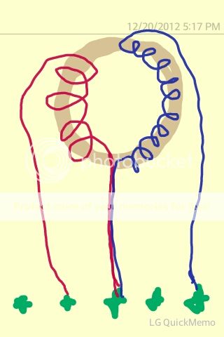
The green dots are the via holes for the secondary windings for the small transformer.
What type of waveform should it have?
I have to have -15/+15 and -35/+ 35, so am assuming I'll need 4 wires that will be turned one pair with more turns (the higher voltage). I hope i got it right.
Does this look right? forgot on the diagram the current limit resistor but it will be added.
The green dots are the via holes for the secondary windings for the small transformer.
Last edited:
Just wind the 5+5 for now. I don't know if the voltage is going to be right so you may have to re-wind them. I'm assuming that you are only showing one winding from each the high and low voltage windings.
It should be a square wave that swings to approximately ±15v.
I don't know if your meter will read the AC voltage on it.
It should be a square wave that swings to approximately ±15v.
I don't know if your meter will read the AC voltage on it.
. I'm assuming that you are only showing
one winding from each the high and low voltage
windings.
Correct, i didn't want to do all four because I'll overlap the turns on the sketch and might confuse you.
I don't know if your meter will read the AC voltage
on i
How come, its a fluke 111 rms. It reads the voltage on all the transformers I've checked.
Oh ok, so this square wave i should get will be high fhz? That way i know what to set the scope to when looking at it.
It's going to be the same frequency that you have on the main transformer. Set the scope to 10v/div and 10us as a starting point.
- Status
- Not open for further replies.
- Home
- General Interest
- Car Audio
- Sony XM-7547, no output, help.