In honor of Nelson, and to make shorts less likely, we will be supplying mica and goop for mounting the active devices in the mini-kits
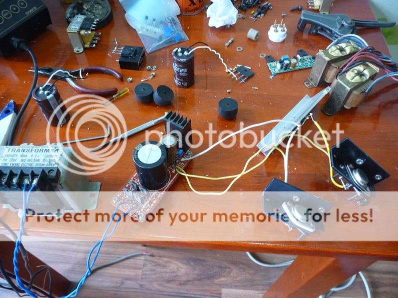
More small parts are being ordered, the final test amp is being built to confirm that all parts fit, as the project continues to creep along.
More small parts are being ordered, the final test amp is being built to confirm that all parts fit, as the project continues to creep along.
Even with BEO it still needs to pass through goop which is way down in comparison.
The quality of the surface of the heatsink is far more important.
The quality of the surface of the heatsink is far more important.
In honor of Nelson, and to make shorts less likely, we will be supplying mica and goop for mounting the active devices in the mini-kits
More small parts are being ordered, the final test amp is being built to confirm that all parts fit, as the project continues to creep along.
Cheers DiyAudio🙂


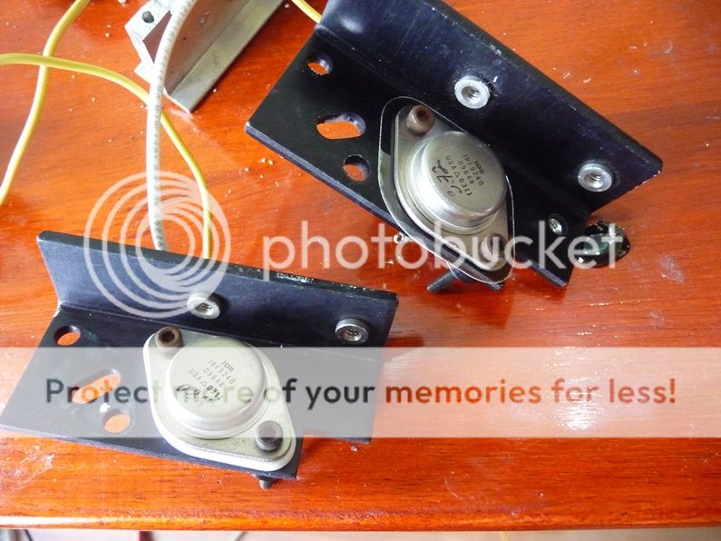
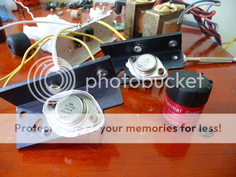
I tested with the same for mica and BeO without goop.
+ IRF9240 (mica) is cooler than IRF9240 (BeO)
+ The heatsink (BeO) is cooler than IRF9240 (mica)
Result: the mica is better than BeO a little bit and I think the reason is BeO is thickness and the mica is thinness, the difference is huge (about 30 to 40 times).
+ IRF9240 (mica) is cooler than IRF9240 (BeO)
+ The heatsink (BeO) is cooler than IRF9240 (mica)
Result: the mica is better than BeO a little bit and I think the reason is BeO is thickness and the mica is thinness, the difference is huge (about 30 to 40 times).


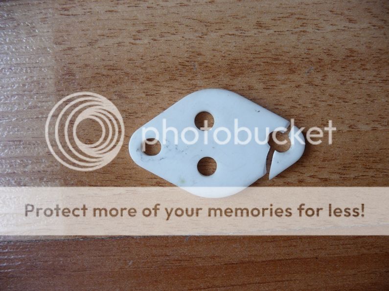
Without goop I think means you are mostly testing how well the surfaces meet up. The mica is smooth and flexes and the BeO doesn't. (that cracked piece is a bit scary, hope you kept away from inhaling any particles!).
Unless the transistor case is radiating signficiantly itself and the BeO insulators hardly conducting at all (not too likely), the heat sink temperatures should have been about the same if the power dissipated is the same and the heatsinks were the same. The relelvant measure, of course, is the device temperature.
Why not do a fair test WITH goop, as that's the only sane way they would be used?
Edit: found my old test of mica vs. alumina --
http://www.diyaudio.com/forums/pass-labs/37262-mica-goop-18.html#post4410496
http://www.diyaudio.com/forums/pass-labs/37262-mica-goop-22.html#post4417290
Last edited:
Cover all surfaces of the BeO wafer with goop [or silicone grease] to trap its loose dust. Any electronic device [commercial or diy] using BeO wafers must show a hazard sticker on its enclosure; like the one assigned in its Material Safety Data Sheet.
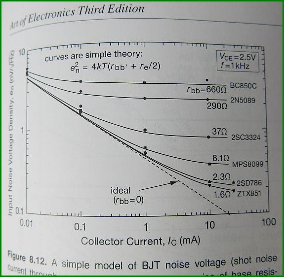
Just discovered ZTX851/951 are much lower in noise compared with BC parts.
Just wondering whether their higher capacitance are a problem for cascode devices? My guess is, it's probably ok given it's in series, but I would like to know before purchasing a stack of them.
Just wondering whether their higher capacitance are a problem for cascode devices? My guess is, it's probably ok given it's in series, but I would like to know before purchasing a stack of them.
Without goop I think means you are mostly testing how well the surfaces meet up. http://www.diyaudio.com/forums/pass-labs/37262-mica-goop-22.html#post4417290
Exactly
not loosing my sleep about noise in this amp
Why am I still awake. Should be bloody sleeping.
Hahahahaha
At 8mA ZTX851 looks very good in regards to noise.
Thanks Jacco for the tip.
Rbb of 1.6 Ohms, good or bad for cascode?
Thanks Jacco for the tip.
Rbb of 1.6 Ohms, good or bad for cascode?
I tested again both with thermal grease and the result is: (touch with my hand)
+ Temperature of two heatsink are very close.
+ IRF9240 (BeO) is a little cooler than IRFP9240 (mica)😛
This is a good result and surface is very important🙂
Thanks for all!
+ Temperature of two heatsink are very close.
+ IRF9240 (BeO) is a little cooler than IRFP9240 (mica)😛
This is a good result and surface is very important🙂
Thanks for all!

Absolutely.This is a good result and surface is very important 🙂
The quality of the 2 mating surfaces is the limiting factor.
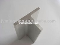
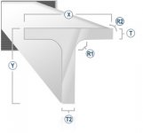
Papa Vfet P2 kit are with aluminium T bracket profiles 😉
An externally hosted image should be here but it was not working when we last tested it.
Attachments

T bracket like this one :
http://www.diyaudio.com/forums/pass-labs/276711-sony-vfet-amplifier-part-2-a-102.html#post4628419

Greetings
http://www.diyaudio.com/forums/pass-labs/276711-sony-vfet-amplifier-part-2-a-102.html#post4628419
Greetings
I tested again both with thermal grease and the result is: (touch with my hand)
+ Temperature of two heatsink are very close.
+ IRF9240 (BeO) is a little cooler than IRFP9240 (mica)😛
This is a good result and surface is very important🙂
Thanks for all!
Can you measure the pin diameter of both the n- and p- IRFs? Mine differ greatly and don't fit the sockets I specified for my boards 🙁
Yeah, the pins are fatter on the IRF240, which is why we used the IRF244
lots of the time.
The IRF240 and 250 are .060" and the 244's are .040"
😎
lots of the time.
The IRF240 and 250 are .060" and the 244's are .040"
😎
Well, IRF244 would definitely solve my problem then! Just "available" from China though, upon cursory glance 🙁
Any reason why the Harris IRF244 parts wouldn't be a good choice? I assume they also have the smaller pin diameter? I would still use the IRF9240 on the other side of the PSU.
- Home
- Amplifiers
- Pass Labs
- Sony vFET Amplifier Part 2