Few matched pairs i am lucky
Soundhappy,
i am so happy for you! Too bad I came late to the game and the ones I got were very far apart. Unless I get lucky, I am building the "hockey puck" amp papa described at BAF2015.
Soundhappy,
i am so happy for you! Too bad I came late to the game and the ones I got were very far apart. Unless I get lucky, I am building the "hockey puck" amp papa described at BAF2015.
Hi Ci11
For simplified one pair version no need matched 2SK/2SJ's.
Papa say it's little less power but sound very similar.
Stay in tune for DiyAudio Store Vfet kit news so you have chance buy one
and build as well is not came to late in reality.
" Hockey puck " i guess can sound marvelous
Hi Ci11
For simplified one pair version no need matched 2SK/2SJ's.
Papa say it's little less power but sound very similar.
Stay in tune for DiyAudio Store Vfet kit news so you have chance buy one
and build as well is not came to late in reality.
" Hockey puck " i guess can sound marvelous
Hi Soundhappy,
I do plan to wait patiently for a kit at the Store. However, even with the kit, the parts count of the VFET amp is significantly higher than the hockey puck amp, and I have most of the parts on hand, including the JT123's - I just have to figure out the heatsink situation. Perhaps I will build both, but in the name of domestic tranquility, that may not be a smart move....
That's why you and others like WalterW with quantities of VFET's are well ahead of the game. I just came too late.
...the parts count of the VFET amp is significantly higher than the hockey puck amp,
and I have most of the parts on hand, including the JT123's...
@ Ci11
Yes smart way to become lucky one too 😉
Attachments

@ Ci11
Yes smart way to become lucky one too 😉
Soundhappy,
Not only are you lucky with having VFET's that match, you live in one the most beautiful places on earth. I still remember being in awe of the pink flamingoes and the incredible food when I visited the Camargue. I knew there had to be a reason a Rolls Royce was named after this place....
I have some matched p-ch pairs and some n-ch singletons. I would like to let some go and buy some more p-ch pairs to get some better matches (or willing to "trade"). Let me know if interested!
I have a pair of kf 28 singles that I'd like to trade for 82 singles . Your mail is full, btw.
Soundhappy,
Not only are you lucky with having VFET's that match, you live in one the most beautiful places on earth. I still remember being in awe of the pink flamingoes and the incredible food when I visited the Camargue. I knew there had to be a reason a Rolls Royce was named after this place....
Haha Ci11 you have visited Camargue !
Wonderful & unique place to have holidays
https://www.youtube.com/watch?v=EVUx6hiGNvg
fascinating like is DiyAudio forum for diy amplifiers

Greetings
Attachments
-
 4BD70286-37B9-43B1-B368-5A628D03BAD7.JPG203.4 KB · Views: 1,133
 -
 D5332B64-E41C-44E4-B477-557A741CFADB.jpg949.1 KB · Views: 1,125
 -
 EB86B121-DC07-4C91-B841-8735324C306E.JPG186.6 KB · Views: 948
 -
 C051A6B5-723F-4A82-9C2A-D689FE15A96D.JPG259.6 KB · Views: 937
 -
 375F1293-DE62-4190-A72C-66B904BC27D9.jpg147 KB · Views: 792
Haha Ci11 you have visited Camargue !
Wonderful & unique place to have holidays
https://www.youtube.com/watch?v=EVUx6hiGNvg
fascinating like is DiyAudio forum for diy amplifiers
Greetings
Soundhappy,
You are bringing back all my very fond memories! The reason I was on the Camargue was to do a shoot (of a beautiful model, of course) on the sand dunes. I stayed in Fontvieille for a month and traveled weekly to the dunes, sometimes stopping in Arles and Nimes. So the arena is a very familiar scene, along with the many Toro restaurants.
Anyway. lest not get too far away from our amplifiers that make fantastic music that moves us all. The good ones remind us of all those wonderful places in your pictures.
Merci beaucoup!
Question for mister Pass 🙂
Why is it that in VFET part1, the CSX1, the VFETs have a 24V and 1.5A bias a piece (=36Watt).
And in VFET part2 the followers have only 19V and 0.5A bias a piece (=9.5 Watt) ?
Is it because of the maximum dissipation of the First Watt chassis?
I ask this because for the 19V 0.5A figure a 2SK60 and 2SJ18 can be a fine substitute, and they are still available.
Walter
If you look at the sink with fan in pt1, you will see that it can keep the
devices nice and cool. Normally I wouldn't want those parts running at
quite that wattage, but with Common-Source / no feedback you need it
for the performance.
If you want to increase the bias on the pt2 circuit, be my guest. I set it up
for moderately hot sinks on a FW chassis.
😎
devices nice and cool. Normally I wouldn't want those parts running at
quite that wattage, but with Common-Source / no feedback you need it
for the performance.
If you want to increase the bias on the pt2 circuit, be my guest. I set it up
for moderately hot sinks on a FW chassis.
😎
Is it wise to put 100 Ohm gatestoppers in, for Q15 and Q16?
Gates go now directly to the wiper of the trimpots P3 and P4.
I made provisions for them in my frontend PCB's, but maybe Papa let them out with a reason?
Gates go now directly to the wiper of the trimpots P3 and P4.
I made provisions for them in my frontend PCB's, but maybe Papa let them out with a reason?
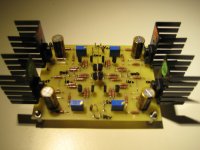
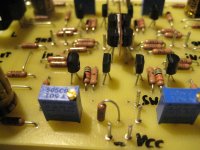
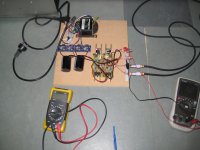
Some progress on the front end.
Everything seems OK, 13 Volts at the JFETs, I can trim the outputs to zero with the pots and bias them to 40mA easily. I used the new values for the resistors which Papa mentioned later on DIYAudio. I have no output capacitor and offset is not very stable, fluctuates with temperature and during warming up. So maybe I should use one.
I run the front end without feedback. Voltage is + and - 35 Volt, a bit high. See pics.
I have a few questions.
1. In the article is mentioned: "
I thought if you give an amp feedback, you loose gain. Here it is both 16 dB? With and without feedback, or is it a typo?
I ask this while it seems like, running with no feedback, my gain seems to be more in the 26dB range then 16 dB. 😕
2. Can I switch in the feedback (for the front end only) with the R23 connected to the output node of R20 and the drains of the MOSFETs?
3. Is the whole VFET pt2 amp DC coupled? Or not because of C5 and C6 between front end and output stage?
But why are there two resistors R41 and R42 paralleled to the capacitors?
Will they pass through some DC to the high ohm-ish gates?
4. What will be the output impedance of the front end with the new Papa values? R22 is 10K 😱 with the new values.
5. Should I give this R20 a lot smaller value when using the frond end as a preamp only? I remember the famous words in the BA-3 article: "Degeneration and getting Loaded". 🙂 In the BA-3 that resistor is 330 Ohm. And lowers ( spoils) the gain.
Hope someone can answer.
Walter
Everything seems OK, 13 Volts at the JFETs, I can trim the outputs to zero with the pots and bias them to 40mA easily. I used the new values for the resistors which Papa mentioned later on DIYAudio. I have no output capacitor and offset is not very stable, fluctuates with temperature and during warming up. So maybe I should use one.
I run the front end without feedback. Voltage is + and - 35 Volt, a bit high. See pics.
I have a few questions.
1. In the article is mentioned: "
If you set R24 at 332 ohms and leave R23/R46 out, the amplifier will have no
global feedback (only local) and deliver gain of about 16 dB. If you switch in
R23 and R46, it will still have 16 dB of gain, but about 3 times the damping
factor and one-third the distortion, corresponding to about 10 dB of global
feedback."global feedback (only local) and deliver gain of about 16 dB. If you switch in
R23 and R46, it will still have 16 dB of gain, but about 3 times the damping
factor and one-third the distortion, corresponding to about 10 dB of global
I thought if you give an amp feedback, you loose gain. Here it is both 16 dB? With and without feedback, or is it a typo?
I ask this while it seems like, running with no feedback, my gain seems to be more in the 26dB range then 16 dB. 😕
2. Can I switch in the feedback (for the front end only) with the R23 connected to the output node of R20 and the drains of the MOSFETs?
3. Is the whole VFET pt2 amp DC coupled? Or not because of C5 and C6 between front end and output stage?
But why are there two resistors R41 and R42 paralleled to the capacitors?
Will they pass through some DC to the high ohm-ish gates?
4. What will be the output impedance of the front end with the new Papa values? R22 is 10K 😱 with the new values.
5. Should I give this R20 a lot smaller value when using the frond end as a preamp only? I remember the famous words in the BA-3 article: "Degeneration and getting Loaded". 🙂 In the BA-3 that resistor is 330 Ohm. And lowers ( spoils) the gain.
Hope someone can answer.
Walter
Attachments
1) The difference is between local and global feedback, the amount of feedback is the same in both cases since the output stage is unity gain (only provides current gain).
Yes, I understand that too, but where does the 10 dB global feedback come from? Only the front end is delivering voltage gain, not the output stage.
Last edited:
I think R24 sets the open loop gain without the feedback (higher R less gain, lower R more gain). When switched in R24 is in parallel with R46 which results in a lower value R to ground and so increases the open gain, which then gets reduced by the feedback.
Please someone correct me if I am wrong. 😱
Please someone correct me if I am wrong. 😱
If the gain is 16dB then open loop gain must be 26dB.Yes, I understand that too, but where does the 10 dB global feedback come from? Only the front end is delivering voltage gain, not the output stage.
26 - 16 = 10dB of feedback
I think R24 sets the open loop gain without the feedback (higher R less gain, lower R more gain). When switched in R24 is in parallel with R46 which results in a lower value R to ground and so increases the open gain, which then gets reduced by the feedback.
Please someone correct me if I am wrong. 😱
I think you are right. With changing the value of R24 you change the gain. In the original part2 article 150 Ohm is parallel to 332 Ohm, this results in 100 Ohm. I tried and gain is higher.
I also implemented a switch, to switch in the feedback resistor of 4k75 only. And it results in around 10 dB lower gain.
Surprisingly also the offset variation gets much (3 times) better 🙂
Feedback makes amplifiers behave better😉
Also the loading of the frontend determines the gain. In the article Nelson says it sees around 1 KOhm but with the new resistor values it will be higher.
So if I drive my DCB1 with this front end, which has 220k inputs, gain values will be different.
I have to experiment more😀
- Home
- Amplifiers
- Pass Labs
- Sony vFET Amplifier Part 2