Rod's write up is great. In order to generate these waves, the advice I found was to start with a 1kHz sine wave with sufficient amplitude to generate 1v across an output dummy load (4R and 8R). Then, do a frequency sweep with your signal generator and watch the output wave forms on your scope. Next, adjust the input amplitude until you get 10v output across your dummy load and repeat. Use both sine waves and square waves. I have written up some of this in the Output Power & Waveform Testing section of my Aleph-X web page.
Thanks a lot, I will have a look...
Quick question: why did the modulated cascode get dropped in the kit vfet amp? I was reading the Zen articles, and I was getting the idea of what it's supposed to accomplish, and I'm wondering why it was eventually omitted here?
My guess, is simplicity, and minimising the risk to the completely irreplaceable parts here, but I thought it worth the question.
Simplicity. Also, this is an area where you are more likely to break the amp
if it heavily clipped, and avoiding that takes even more parts.
I'm not Nelson, but I'll offer a guess - the output stage regulators eat up about 8v of each rail and make the rail voltage approximately 20V, but offer the advantage of making the rail very quiet and being able to sequence the power up and power down as required to keep the Vfet happy. The cascode isn't necessary for safe Vfet operation.
Simplicity. Also, this is an area where you are more likely to break the amp
if it heavily clipped, and avoiding that takes even more parts.
Thanks for the explanations! Much appreciated. I'd best get on with my build then!
Apologies if this is OT. I'm thinking this wonderful amp may not have quite enough ooomph for my FH3s.
Any preamp recommendations?
Any preamp recommendations?
BA-3 pre, LSK pre, Juma's LSK pre are 3 that I have tried and work great among others. Depending on your driver for the FH3, room, listening volume I think they would do fine, at least for most. The general consensus among most users of Firstwatt products is 90db or better.
bridging the outputs
can someone please answer this question:
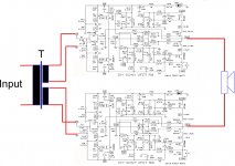
can the outputs of this amp get bridged if one need more output power? if yes, what is the best way to do that and what would be the expected performance at 8 ohm (watt per mono-block)?
best regards
can someone please answer this question:
can the outputs of this amp get bridged if one need more output power? if yes, what is the best way to do that and what would be the expected performance at 8 ohm (watt per mono-block)?
best regards
You can take two channels with a common ground and drive each of
them with signal out of phase with the other. Generally the performance will
be twice the power of the 4 ohm rating of a single channel.
them with signal out of phase with the other. Generally the performance will
be twice the power of the 4 ohm rating of a single channel.
You can take two channels with a common ground and drive each of
them with signal out of phase with the other. Generally the performance will
be twice the power of the 4 ohm rating of a single channel.
many thanks, nelson.
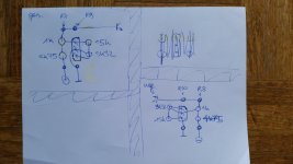
is the attached diagram correct?
any other (internal) option in order to avoid the external phase splitter (input transfomer)?
best regards
Attachments
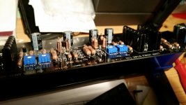
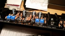
Alright, here's a sneak preview of my ongoing build. I really felt like having the shunt regulator circuit for the cascode transistors from the Sony VFET Part 2 article, so I built a nice p2p subcircuit that plugs right into the pcb. I also happen to like big fat resistors, so I'm using RN60D types throughout. For the feedback path and frontend loading like even bigger and fatter resistors, so I'm using RN65E types. I should get around to finishing and biasing the frontend tomorrow, we'll see how it goes.
Attachments

Alright, here's a sneak preview of my ongoing build. I really felt like having the shunt regulator circuit for the cascode transistors from the Sony VFET Part 2 article, so I built a nice p2p subcircuit that plugs right into the pcb. I also happen to like big fat resistors, so I'm using RN60D types throughout. For the feedback path and frontend loading like even bigger and fatter resistors, so I'm using RN65E types. I should get around to finishing and biasing the frontend tomorrow, we'll see how it goes.
Could you post details of this subcircuit?
Can anybody advise me on why I only have .9v on T4 all resistors are correct and all other test points are spot on. T2 is 24v
Are there any news?
No.....I still trying to figure it out it seems odd that all other test points are spot on except
T4 ????
T4 ????
Have you tried replacing R20? If T4 is at -0.9V and T1 at -28V (all ref ground)
then there's over 27V drop across R20 (2.21K) and the power dissipation will be
around 0.33W. If it's a 1/4W resistor it may be damaged and no current is
going through to the Q14 TL431.
Dennis
then there's over 27V drop across R20 (2.21K) and the power dissipation will be
around 0.33W. If it's a 1/4W resistor it may be damaged and no current is
going through to the Q14 TL431.
Dennis
- Home
- Amplifiers
- Pass Labs
- Sony vFET Amplifier Part 2