Not wanting to sound like a broken record here but the fact that noise returns when it cools would indicate that targeted cooling with freeze spray when the amp is hot (and presumably silent) might help you narrow things down a tad ... hope you find the source soon 🙂
Not wanting to sound like a broken record here but the fact that noise returns when it cools would indicate that targeted cooling with freeze spray when the amp is hot (and presumably silent) might help you narrow things down a tad ... hope you find the source soon 🙂
Absolutely the way to do it if you have some 🙂
In the UK the price of freezer became extortionate. RS want between £12 to £30 a can. It is (or was, as I haven't bought any for ages) cfc134a, the same gas as used in air conditioning systems.
Ouch that is expensive !!
This maybe a cheaper option in North America... FREEZE SPRAY, 10 OZ CAN | AllElectronics.com
This maybe a cheaper option in North America... FREEZE SPRAY, 10 OZ CAN | AllElectronics.com
To be sure what happens is that on power up she is silent then after about 20 minutes or so it starts getting noisy. So, would I then start to hit each component at that point with the freeze?
Update: I took out the Balance Trim Pots and cleaned the contacts with a fine emery board switched them around and still noisy.
Update: I took out the Balance Trim Pots and cleaned the contacts with a fine emery board switched them around and still noisy.
Yep .... That's what I'd try .... Components, connectors pretty much everything between the input RCAs and the output binding posts.
I was told that for some kinds of freeze spray, best results are obtained if you also take a deep breath at the same time as you squeeze the trigger. I of course, haven't the foggiest idea what they're talking about
I was told that for some kinds of freeze spray, best results are obtained if you also take a deep breath at the same time as you squeeze the trigger. I of course, haven't the foggiest idea what they're talking about
Last edited:
Essentially yes.
The secret with freezer is to press the trigger so little that only a single raindrop sized blob appears on the end of the straw which you then drop onto the component. If you blast away it will chill such a large area that you can be non the wiser.
We've still got the question mark over that double diode ? and that was in the area you were working in when you thought it had gone quiet. That's a very big clue and well worth looking at. Any silicon diodes would do to prove it.
(I'd have to look more closely but I think it would work by removing D101 completely and connecting a wire link from the base of Q104 to the base of Q204 such that both channels share the same diode. The diode is used simply as a reference voltage generator. Two diodes at 0.65 volts dropped give around 1.3 volts. If you haven't any diodes then it might be worth trying that to prove it)
And don't forget that "Canned Air" when turned upside down will emit....you guessed it...freeze spray.
I have been using canned air spray for cooling components. Seems to work pretty well, though probably less controllable than real freeze spray
I just picked up the real thing (freeze spray that is) and will have a go this evening. Fingers crossed🙂
Mooly before I go messing around with that diode I'll do the spray thingy first and take it from there. I feel, as you said earlier "a need to be systematic".
Mooly before I go messing around with that diode I'll do the spray thingy first and take it from there. I feel, as you said earlier "a need to be systematic".
OK 🙂
Just try one drip/blob of the freezer on the diode when the fault occurs. If that's no good then try the same on the smaller transistors and a quick squirt on the larger driver transistors Q110 and Q111. Also those small caps I mentioned in post #31
Good luck... hope it finds something but if not we don't give up that easily 😀
OK report. Last night got fired her up and got the noisy LC. My first thing was to squirt D101 and right away silence. Good so far. Like any good scientist we need to repeat our findings to be sure. Thing is now when I try to repeat this the amp only fires up with a short burst of static and then silence. The freezing of D101 seems to have had an effect, confusing since this is only diagnostic in nature and not a fix.OK 🙂
Just try one drip/blob of the freezer on the diode when the fault occurs. If that's no good then try the same on the smaller transistors and a quick squirt on the larger driver transistors Q110 and Q111. Also those small caps I mentioned in post #31
Good luck... hope it finds something but if not we don't give up that easily 😀
It does seem to me that I do need to get D101 and D102 out of there. I could run a couple of diode in series as you recommend. I'll need to order those. I do have tans on the way along with resistors as well.
Definitely suspect is that diode. Freezing any [good] component should have no effect. Don't worry that freezing it seems to have changed or altered things... that happens sometimes if the part is faulty... the freezing will have altered it in some way.
My only concern is that you shouldn't really use the amp while its like this because if the fault became permanent then the result could be a large DC offset which would zap the amp and speakers. The diodes (1N4148 type) should be available anywhere.
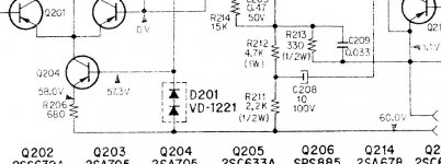
Also, looking at the circuit and the voltages given don't quite tally with what I would expect for a "double diode" so can you measure the voltage across D201 (the good one) If you look at the circuit it shows 60 volts as the supply rail and 57.3 volts on the base of the transistor which implies 2.7 volts across the diode. If there is 2.7 volts across the diode then its no problem... we use something different 🙂
My only concern is that you shouldn't really use the amp while its like this because if the fault became permanent then the result could be a large DC offset which would zap the amp and speakers. The diodes (1N4148 type) should be available anywhere.
Also, looking at the circuit and the voltages given don't quite tally with what I would expect for a "double diode" so can you measure the voltage across D201 (the good one) If you look at the circuit it shows 60 volts as the supply rail and 57.3 volts on the base of the transistor which implies 2.7 volts across the diode. If there is 2.7 volts across the diode then its no problem... we use something different 🙂
Attachments
Definitely suspect is that diode. Freezing any [good] component should have no effect. Don't worry that freezing it seems to have changed or altered things... that happens sometimes if the part is faulty... the freezing will have altered it in some way.
My only concern is that you shouldn't really use the amp while its like this because if the fault became permanent then the result could be a large DC offset which would zap the amp and speakers. The diodes (1N4148 type) should be available anywhere.
Also, looking at the circuit and the voltages given don't quite tally with what I would expect for a "double diode" so can you measure the voltage across D201 (the good one) If you look at the circuit it shows 60 volts as the supply rail and 57.3 volts on the base of the transistor which implies 2.7 volts across the diode. If there is 2.7 volts across the diode then its no problem... we use something different 🙂
I have replaced the Diodes (now need to check the voltages) and replaced the Trannies as well (2N5401). Sounding good I have to say.
Last edited:
I read 60V on either side of the diode grounded. Reading 60V on the Base of the Q101. No noise.
Last edited:
Well that's sounding promising I must say 😀 Your well ahead of me.
The diode voltage I mentioned has to be measured across the device for accuracy rather than from ground. If you do... be careful 🙂
All the diodes do is allow a known and predictable voltage to develop across them. Any silicon junction drops around 600 millivolts when conducting and so two diodes drop 1.2 volts. In combination with the transistor and its emitter resistor a near perfect current source is formed. The transistor B-E volt drop is around 600 millivolts and so we are left with 0.6 volts across the 680 ohm emitter resistor. No matter what the 60 volt rail does that current in the 680 ohm is unchanged.
Well that's sounding promising I must say 😀 Your well ahead of me.
The diode voltage I mentioned has to be measured across the device for accuracy rather than from ground. If you do... be careful 🙂
All the diodes do is allow a known and predictable voltage to develop across them. Any silicon junction drops around 600 millivolts when conducting and so two diodes drop 1.2 volts. In combination with the transistor and its emitter resistor a near perfect current source is formed. The transistor B-E volt drop is around 600 millivolts and so we are left with 0.6 volts across the 680 ohm emitter resistor. No matter what the 60 volt rail does that current in the 680 ohm is unchanged.
I measure 60V across the diode and I think I follow what you are saying.
Do you think I have it now? Does this all shape up? Still no noise🙂
The fact its all working is promising. Yes I think the diode could well have been the issue.
The voltage across the diode should be around 1.2 volts for your new combination of two series diodes. The measurement isn't ground referenced 🙂 It's with one lead on one end of the diode and the other lead on the other end 🙂 I was curious to know what the old but good diode read when measured like this. But be careful !
The voltage across the diode should be around 1.2 volts for your new combination of two series diodes. The measurement isn't ground referenced 🙂 It's with one lead on one end of the diode and the other lead on the other end 🙂 I was curious to know what the old but good diode read when measured like this. But be careful !
The fact its all working is promising. Yes I think the diode could well have been the issue.
The voltage across the diode should be around 1.2 volts for your new combination of two series diodes. The measurement isn't ground referenced 🙂 It's with one lead on one end of the diode and the other lead on the other end 🙂 I was curious to know what the old but good diode read when measured like this. But be careful !
1.3V 🙂🙂🙂
Yay 🙂
Now is that the new one or the old one in the other channel ?
Well, I swapped both out at the same time😱 So it's both the new ones, again 😱
- Status
- Not open for further replies.
- Home
- Amplifiers
- Solid State
- Sony TA3200f Issue