Hi All,
Me and Jeff decided to start a separate thread on the amps, based on original VHex.
Here is the first one - VHex+BT (BiTurbo).
Key differences with original VHex:
- slightly updated front-end - symmetric current-drive, providing higher speed and linearity;
- bootstrapped drivers, allowing higher output swing with the same rails;
- no bias spreader - thermal feedback is provided by the drivers.
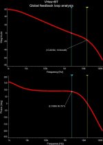
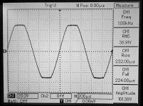
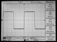
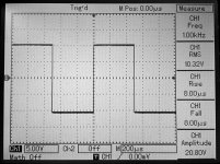
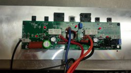
At the moment this design is fully prototyped and live tested (see the measurements, screenshots and pictures).
Its a kind of CFA-fast VFA, having excellent step response, clean clipping close to the rails and pretty good distortion profile.
The sound is excellent to my taste - very natural, full of micro-details, having articulated, rich bass at the same time.
PCBs and kits are available.
The other design in the family - VTrench - same size PCB with OPS "on steroids" will follow soon (same level of quality at some 300W output power).
Stay tuned!
Cheers,
Valery
Me and Jeff decided to start a separate thread on the amps, based on original VHex.
Here is the first one - VHex+BT (BiTurbo).
Key differences with original VHex:
- slightly updated front-end - symmetric current-drive, providing higher speed and linearity;
- bootstrapped drivers, allowing higher output swing with the same rails;
- no bias spreader - thermal feedback is provided by the drivers.
At the moment this design is fully prototyped and live tested (see the measurements, screenshots and pictures).
Its a kind of CFA-fast VFA, having excellent step response, clean clipping close to the rails and pretty good distortion profile.
The sound is excellent to my taste - very natural, full of micro-details, having articulated, rich bass at the same time.
PCBs and kits are available.
The other design in the family - VTrench - same size PCB with OPS "on steroids" will follow soon (same level of quality at some 300W output power).
Stay tuned!
Cheers,
Valery
Attachments
-
 00-VHex+BT-Sch.jpg155.3 KB · Views: 4,394
 -
 YHex+BT AC Sweep.jpg58.2 KB · Views: 1,823
 -
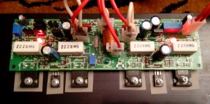 VHex+BT Prototype 01.jpg183 KB · Views: 1,624
 -
 DSC_0404.JPG474.2 KB · Views: 749
 -
 DSC_0402.JPG478.9 KB · Views: 667
 -
 DSC_0400.JPG443.4 KB · Views: 784
 -
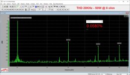 02-THD-20K-50W.JPG275.3 KB · Views: 3,058
 -
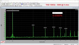 02-THD-10K-50W.JPG277.7 KB · Views: 3,216
 -
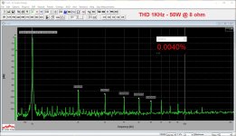 02-THD-01K-50W.JPG288.5 KB · Views: 3,420
 -
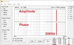 01-Bode-10Hz-100KHz.JPG104.3 KB · Views: 4,160
Here's a teaser of the VTrench. I have a tester running on a scrap of aluminum with a measly +/- 70V supply feeding it. Valery described the sound perfectly in the previous post. "Very natural, full of micro-details, having articulated, rich bass at the same time." I'm very impressed with the sound and the power of this little amp. Proper testing is awaiting some heatsink and a supply worthy of this thing.
Attachments
Hello vzaichenko
greetings very nice high end amplifiers is it possible for you to post
clear schematic of VHEX+ SCHEMATIC
warm regards
Andrew
greetings very nice high end amplifiers is it possible for you to post
clear schematic of VHEX+ SCHEMATIC
warm regards
Andrew
IXTK 120N25 monster mosfet
The "red haired step brother with the attitude problem" of the VHex family. It is a little monster!😀
Hi Valery
Congratulations on another successful project!
Is there any particular reason why you return the collectors of the folded drivers to the rails instead of the output node? When strapped to the output, the drivers pass very little Vce and you can use high speed, very high gain small signal transistors to take advantage of the HexFet's speed and reduce loading on the VAS even more. I first saw this technique demonstrated by Bob Cordell and I've used it very successfully in a couple of my projects.
IXTK 120N25 monster mosfet
I don't understand how to take advantage of the enormous power dissipation (Pd = 730W!) claimed in the datasheet for this "monster mosfet". Even assuming an infinitely large aluminum heat sink, the thermal resistance between that TO-264 heat spreader and the heat sink is going to make it impossible to dissipate all those watts without the junction temperature soaring sky high!
I don't understand how to take advantage of the enormous power dissipation (Pd = 730W!) claimed in the datasheet for this "monster mosfet". Even assuming an infinitely large aluminum heat sink, the thermal resistance between that TO-264 heat spreader and the heat sink is going to make it impossible to dissipate all those watts without the junction temperature soaring sky high!
Heatpipes and water cooling!!!
Thats's the problem isn't it? How to utilise the Power Dissipation ratings of these monster fets without resort to water cooling or other exotic methods. Matching parallel fets is difficult and I'd like to be able to use a single pair to build a high power amp but I'm not convinced these switching fets are up to the task.
All the online PC fab houses charge the same for 1 layer or 2 layer so it's not a big deal for those of us that send out for our boards. I guess for hone etching it's an extra step or double the work.
Terry, two layer pcbs are a pretty much a necessity for surface mount
I use smd all the time on single sided boards.
All the online PC fab houses charge the same for 1 layer or 2 layer so it's not a big deal for those of us that send out for our boards. I guess for hone etching it's an extra step or double the work.
I have piles of unused boards from board houses. They are best for those who are building amps for use. For building for testing, home etched boards are quick and cheap and fun. I have more amps then I can ever use. It is Valery's choice of course. He is doing the real work. I'm just here to learn and have fun.
Blessings, Terry
Hi Terry
I wasn't suggesting that its impossible to lay out a single-sided board using SMD parts, but it sure is going to be difficult unless one accepts mixing in through-hole parts (or through-hole jumpers).
I wasn't suggesting that its impossible to lay out a single-sided board using SMD parts, but it sure is going to be difficult unless one accepts mixing in through-hole parts (or through-hole jumpers).
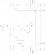
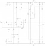
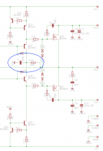
That looks very nice Valery. Can you please highlight which part of the IPS is different?
Hi X,
See the pictures - the left one is original VHex front-end, the right one - the updated version, utilizing the currents of both LTP shoulders and driving the both output CCSs - the top one and the bottom one. In both cases, the whole thing is controlled only by currents, converting to voltage swing only at the output of the front-end. The second version is slightly more balanced, precise, fast and linear.
Attachments
Hello vzaichenko
greetings very nice high end amplifiers is it possible for you to post
clear schematic of VHEX+ SCHEMATIC
warm regards
Andrew
Hi Andrew,
Do you mean the one from post #1 here (VHex+BT), or the original VHex+ one?
Hi Valery
Congratulations on another successful project!
Is there any particular reason why you return the collectors of the folded drivers to the rails instead of the output node? When strapped to the output, the drivers pass very little Vce and you can use high speed, very high gain small signal transistors to take advantage of the HexFet's speed and reduce loading on the VAS even more. I first saw this technique demonstrated by Bob Cordell and I've used it very successfully in a couple of my projects.
Hi Ranchu,
In fact, I had the collectors connected to the bootstrap points initially - rather elegant solution at a first glance. But initial testing revealed an interesting issue - after I switched off the power, the rails voltage started going down, and at some point, as soon as it reached the point when the front-end (and NFB) stopped working, I saw high-frequency oscillation at the output - local OPS oscillation. Not catastrophic, but not good. So, I have connected those collectors to the rails and slightly reduced their operating currents. This configuration is less efficient, but rock stable.
Connecting them to the output node, as you're suggesting - also an interesting option, but requires a bit more research and careful testing.
Wanna try? Be my guest 😉
- Home
- Amplifiers
- Solid State
- Sons of VHex