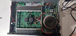
Hey diyAudio community! Just ended up with my own Sonamp 260 MKII dated 09/02. Little dude rocks! I also ended up with BOMs and schematics dated Oct 22, 2001 REV A.
I would like to use this little guy as my first involved restore/modification/research project. I have read this thread several times and think I follow most the basics. I have already unplugged and unsoldered the brown and orange wires going to the red LED. Replaced the input board jrc4558dds with lm4562s with so so results, haven't been able to turn it up overly loud yet.
Currently in the process of trying to recap every Lenor electrolytic as I hear they are notoriously garbage. I'm wondering if they are the cause of my slight transformer hum and slightly higher right channel offset measured at the speaker output?
I am having an electrician at work look over the amp and schematics with me and hopefully help me ID what caps are filter and what are coupling so I order correct caps for audio and power paths respectively. He admitted audio circuitry isn't his realm though, he's 12v.
Input buffer and auto on bypass. I do believe I am understanding correctly in that later models like mine and mrpdevivo cannot bypass the input buffer board without also swapping the power switch and bypassing the relay? I'm not sure I'd know how to determine the correct switch. Otherwise I'm fairly comfortable following the instructions profiguy gave earlier. Though never I've messed with power supplies.
Finally I would like to adjust bias to at least 5mV like others have suggested. I have never performed a bias before either. I am assuming this is done with adjusting the 2 small pots on the main board? Where are the ".33R emitter resistors" mentioned? I know they come after transistors but I can't quite peg them down yet. I am just using my multimeter across said resistor legs and adjusting correct?
My apologies for the length and possibly ignorant questions. I know it's only a thrift store score but it's a currently working one and I'd like to make sure I understand before serious desoldering and modifying. Thanks all, I look forward to being a part of the diy community!
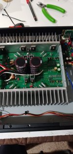
Well I recapped it using this thread as a guide. I also replaced all of the Mylar caps with PET equivalents and replaced any electrolytic 4.7uf and under with film equivelents. What a difference it made! I did the input board first just to see and that alone made a world of difference. I will still bypass it at some point though.
I did not however replace c801/901. On my factory BOM as well as verified on the board as 1uf 63V metal oxide film caps, not 4.7 uf as previously mentioned here. I'm wondering if that's a difference in old vs. MKII boards? If so would I be better off sticking with film here and going from 1uf to a 4.7 uf? It is the same rough 4.6 times increase as going from 4.7uf to 22uf right?
I located the emitter resistors and noticed they are paired up and in 4 sets. Am I supposed to be looking for 5mV at each resistor? Is 5mV still a reasonable target for the MKII versions with topologies being different?
Attachments
Update and hopefully useful info for someone with a MKII 260 in the future.
I have bypassed the input board by soldering the signal leads to the bottom of the pcb at the RCA jack. Soldered the ground lead to the ground post the lift switch uses. Now going straight to the amplifier board.
I believe I have also bypassed the auto on circuit without needing to lift the legs of C401/501. On the input board there are 3 small black jumpers connecting 2 of 3 available pins each. You can mostly see them in the first 2 pictures I posted above.
JP001 is H Sens and I removed it. JP401/501 are Hi Pass ON-OFF for L and R channels. I moved both from ON to OFF. I also removed both op amps from the board just to help verify bypass. Everything has been running fine for a while now with no start up or shut down issues. Another noticeable increase in sound quality and openness to boot. A volume boost too according my preamp.
Though maybe not as thorough as removing the board board completely. It seems to be a viable option for MKII people without the ability to replace the power switch.
Not sure if those jumpers are there for diagnostics or the engineers were cool enough to give us those bypass options to start but seems to do the trick!
Many thanks to @ostripper for his modeling and guidance on improving the Sonance 260. I got 2 260s early this past summer (not Mk 2s, but older ones, just the same as Vunce’s units with the light brown PCBs and the orthogonal arrangement of emitter resistors) and had done input PCB bypass for signal, and the C901-C801 to Muse equivalents on the main board (many thanks to @profiguy and @mp20748 for these), and was very pleased with the results.
In the past week I have made the C903-C905/C803-C805 upgrades to silver mica 270pF-15pF, the resistor 9xx-8xx changes to 100Ω, the extra 0.1µF decoupling caps for the rails (I used Panasonic ECQ mylar), and added 1µF ECQ across R915/R815 (didn’t have any 0.47µF). It is always a challenge to provide subjective evaluation as a result of these last changes, but I can say I have never enjoyed these units as much as I do now. They are somewhere between enticing and mesmerizing with the right speakers (DCM TimeWindows in my case).
I have two questions for ostripper, if you are willing:
— What is the purpose of the 0.47µF addition across R915/R815? You didn’t mention anything about them in earlier posts, beyond them appearing in the schematic, and I am curious. I’d also like to know if going to 1µf here is OK; I can't fault the sound I am hearing with them.
— I also have 2 Sonance 275SE amps I acquired a few years ago. These are later than the 260 models, but share a surprising about of circuitry with them. I have already modified them a bit: the BBE front ends are not so amenable to modification (mostly SMD, and dependence of circuitry downstream mitigates against outright bypassing), but there are two through-hole input coupling caps on that board, and I changed those to Muse equivalents (they are followed by LF353 op amps, so perhaps not so bad). I also changed the poor quality YEC 4.7µf input coupling caps on the main PCB (C901/C801) to Muse equivalents.
These changes were all for the better, but now, given the similarity of the 275SE circuitry (see below) to your 260 EF-2 schematic, I’m wondering if some further improvements can be made, namely the lead-lag cap changes in the feedback circuit and the 150Ω->100Ω VAS resistor changes.
Below is a schematic for the 275SE, which appeared a year or so ago at HiFiEngine. My reading of this is that for lead-lag, C906/903 (10pF and 330pF 500V) here is the equivalent of C905/C903 in the 260, and that the 150Ω resistor positions follow directly.
I’ll also note that in the area between the output transistors and the Zobel, the 275SE circuit matches your EF-2 schematic well, but that the 260 version that I and Vunce have, has additional components are located there. Because of those differences, I checked my 260s for where the feedback circuit was taken off at the output end, and it was at the junction between the emitter resistors and the large inductor, so no fix is needed there.
In any event, any enlightenment you can provide on the 275SE vis-a-vis your 260 mods would be much appreciated.
Thank you again for your earlier posts, as they have not only increased my enjoyment of the 260s greatly, but have prompted me to learn more about the purpose of different kinds of circuits in amplifiers.
Attachments
Last week I went ahead and made ostripper-inspired changes to a Sonance 275SE, mostly as I indicated in the above post.
— Changed the feedback caps to 15pF-270pF (C906 C903, C806 C803), this time using MLCC Kemet Goldmax 300 Series COG Class 1 (C317, ±5%, 100V versions, specifically). I used these instead of the silver micas to save some money (I still have a few more units I’d like to do), and I trust/hope they are precise enough and have a high-enough quality dielectric to be up to the task here.
— Changed the 3x 150Ω resistors on each channel to 100Ω. Before making this change, the current across R911 and R811 measured at 1.4mA each, much lower than the >2mA levels ostripper recommended for the similar circuit in the 260. With the 100Ω resistors in place and bias adjusted, the current is now 2.1mA.
— Replaced additional electrolytic caps (I had already replaced the 4.7µF YEC input caps C901 C801 to 10µF Muse two years ago): C001 C011 C012 C904 C804 BP YEC-brand caps changed to Muse or Panasonic BP, C008 to Nichicon UKL. I left C002 C003 alone as they were Nippon Chemicon and tested fine.
There was no need to add 0.1µF film caps for decoupling the PS rails because they already exist in the 275SE (C915 916; C815 C816 on the Main PCB; see the full schematic in post #44).
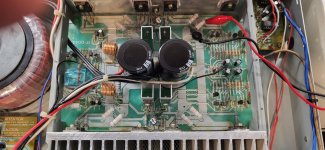
Here is the Main PCB-heatsink assembly, removed from the chassis, before work started. There are many similarities to the 260, but some important differences. There are 3 pairs of output transistors per channel (Sanken 2SA1943/2SC5200) vs. the 2-pairs per channel in the 260 (2SA1942/2SC3856). There is also a near-dual mono arrangement with each channel having its own bridge rectifier and pair of PS filter caps.

In the event it helps anyone in the future wishing to make these changes, here is part of the schematic (post #44) with the components I changed marked with colored rectangles, followed by a close up of the PCB with those components marked with the same colors. The photo was also taken before the current work started (the green Muse caps on the signal inputs were installed earlier, in 2023).


Lastly, I got up the pluck to completely bypass the BBE input PCB and the front panel circuits (input level pots, LEDs, etc.) by directly wiring a new signal cable from the input RCAs on the BBE board to the signal input connector on the Main PCB. I also disconnected (1) the ribbon cable that connects to the BBE board to the front panel (this leaves the BBE unpowered and isolated), and (2) the old signal cable from the front panel back to the input connector on the Main PCB.
I had shied away from attempting to bypass the BBE PCB a few years ago because I did not fully understand what the BBE did, but I have since become more convinced that it was nothing essential to me, and that the key protections for the amp are handled elsewhere. So I was delighted to find that the 275SE runs perfectly fine (for me) with the BBE unpowered, albeit with (1) disabled line-out RCAs (on the BBE), (2) disabled input level adjustment pots (front panel), and (3) disabled clipping and signal-presence LEDs (front panel). The RCA-outs and the LED indicator functionality should be able to be restored by simply reconnecting the ribbon cable, if desired.
With bias is set at 16-17mV, the heatsinks are slightly warm (~36°C in a 23°C/65°F ambient room), and it sounds wonderful.
I am quite pleased with the outcome, and I am happy to confirm that @ostripper 's mods for the 260 are essentially directly transferable to the 275SE.
Thanks again to ostripper for all the info and the inspiration from his work on the 260, without which most of what I did above could not have happened.
— Changed the feedback caps to 15pF-270pF (C906 C903, C806 C803), this time using MLCC Kemet Goldmax 300 Series COG Class 1 (C317, ±5%, 100V versions, specifically). I used these instead of the silver micas to save some money (I still have a few more units I’d like to do), and I trust/hope they are precise enough and have a high-enough quality dielectric to be up to the task here.
— Changed the 3x 150Ω resistors on each channel to 100Ω. Before making this change, the current across R911 and R811 measured at 1.4mA each, much lower than the >2mA levels ostripper recommended for the similar circuit in the 260. With the 100Ω resistors in place and bias adjusted, the current is now 2.1mA.
— Replaced additional electrolytic caps (I had already replaced the 4.7µF YEC input caps C901 C801 to 10µF Muse two years ago): C001 C011 C012 C904 C804 BP YEC-brand caps changed to Muse or Panasonic BP, C008 to Nichicon UKL. I left C002 C003 alone as they were Nippon Chemicon and tested fine.
There was no need to add 0.1µF film caps for decoupling the PS rails because they already exist in the 275SE (C915 916; C815 C816 on the Main PCB; see the full schematic in post #44).
Here is the Main PCB-heatsink assembly, removed from the chassis, before work started. There are many similarities to the 260, but some important differences. There are 3 pairs of output transistors per channel (Sanken 2SA1943/2SC5200) vs. the 2-pairs per channel in the 260 (2SA1942/2SC3856). There is also a near-dual mono arrangement with each channel having its own bridge rectifier and pair of PS filter caps.
In the event it helps anyone in the future wishing to make these changes, here is part of the schematic (post #44) with the components I changed marked with colored rectangles, followed by a close up of the PCB with those components marked with the same colors. The photo was also taken before the current work started (the green Muse caps on the signal inputs were installed earlier, in 2023).
Lastly, I got up the pluck to completely bypass the BBE input PCB and the front panel circuits (input level pots, LEDs, etc.) by directly wiring a new signal cable from the input RCAs on the BBE board to the signal input connector on the Main PCB. I also disconnected (1) the ribbon cable that connects to the BBE board to the front panel (this leaves the BBE unpowered and isolated), and (2) the old signal cable from the front panel back to the input connector on the Main PCB.
I had shied away from attempting to bypass the BBE PCB a few years ago because I did not fully understand what the BBE did, but I have since become more convinced that it was nothing essential to me, and that the key protections for the amp are handled elsewhere. So I was delighted to find that the 275SE runs perfectly fine (for me) with the BBE unpowered, albeit with (1) disabled line-out RCAs (on the BBE), (2) disabled input level adjustment pots (front panel), and (3) disabled clipping and signal-presence LEDs (front panel). The RCA-outs and the LED indicator functionality should be able to be restored by simply reconnecting the ribbon cable, if desired.
With bias is set at 16-17mV, the heatsinks are slightly warm (~36°C in a 23°C/65°F ambient room), and it sounds wonderful.
I am quite pleased with the outcome, and I am happy to confirm that @ostripper 's mods for the 260 are essentially directly transferable to the 275SE.
Thanks again to ostripper for all the info and the inspiration from his work on the 260, without which most of what I did above could not have happened.

Hi folks,@mpdevivo - just clip the red and white wires coming from input board and solder white to r501 / red to r401, then remove or lift one pin on both c401 / c501 4.7uf electrolytics. You will also want to use good non polar electrolytics to replace C801 / C901 4.7uf lytics like nichicon muse series and increase their values to at least 22uf for better LF phase linearity and lower cutoff. You could also add some smaller 470nf PP film caps parallel across them.
The Achilles heel of this amp are the main filter caps. They are underrated in voltage and can go bad prematurely. The supply rails are running close to +/- 50V and the caps are rated 50V. I have 2 of these 260 amps for testing speakers and both amps had bulging PS filter caps. I couldn't find 15000uf / 63V versions at the time so I used 10000uf / 63V which were a little taller size but they fit just fine under the cover of the amp. I dont notice any difference in SQ between the 2 cap sizes and also can't measure any more appreciable supply ripple at lower drive impedances. It may be the replacement caps have lower internal R. Either way, these little 260s sound pretty good for cheap bargajn amps. I found them for only 20 bucks each at a thrift store.
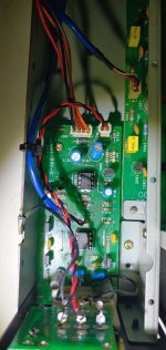
I am new to the forum and have been lurking around for a couple of weeks now.
I recently picked up one of these amps at a local thrift for about $15.00. It sounds great as is, but my intent is to recap this unit and give it to my teenage nephew who is just getting into audio. But after reading through this thread, it appears it can be made even better. However, I am having a difficult time understanding all that is going on in this thread specifically, and I am looking for some clarification. It seems like there are a couple of different conversations going on.
I'd like to make the few subtle changes that @profiguy has suggested, but I am a little confused about his comments.
In the post above he says; "just clip the red and white wires coming from input board and solder white to r501 / red to r401, then remove or lift one pin on both c401 / c501." Then in post #22 he says "You want to connect before the resistors since they're a part of the HF lowpass of the turn on board and aren't needed, as the main amp pcb has an input LP on it as well."
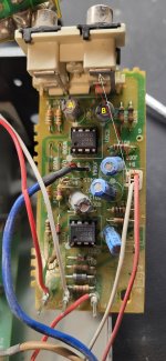
So, do I just unplug the connector from this board (which I assume is the input board), cut the end and solder the red and white wires to the RCA inputs (arrows on the attached pic)? Is that the same as soldering to r40/r501 (A&B on the pic)? If not soldering to the inputs, what is considered before the resistor? Is that towards the back of the board where the lettering is, or closer to the leg with the op amp?
Also, instead of unsoldering just one pin on C401 and C501 (A&B in the pic), can I just remove them altogether if they are not needed?
Any replies would be much appreciated. Thanks in advance for the help!
Attachments
I'm away on travel this week and can only check here infrequently, so if profiguy isn't able to respond, let me try. Your basically have things correct but have misidentified the proper red and white audio leads. The audio signal leads are in the blue-sheaved cable in the middle of the board. L, R, and Ground are labeled in the silkscreen there. Leave the ones you have labeled alone.
I left the ground lead alone, and jumpered L and R wires on the cable to the RCA fittings. Please verify you have chosen the correct spots on the RCAs for that (I always forget on those fittings and trace it out each time). Doing it this way is the same as connecting to "before the resistor", which is where the signal enters the resistor on the schematic, the end that is physically next to the RCAs.
Yes, the two coupling caps can just be removed.
If you also want to bypass the front panel level controls, etc., you can reroute the other end of the blue-sheaved audio cable directly to the main board. I don't recall if L and R are reversed if you use the original fitting (I think they are), but if so, you can compensate for that when you do the jumpering discussed above. As I recall, I did that because I wanted to preserve the blue-sheaved cable and its nice shielding.
I'm away on travel this week and can only check here infrequently, so if profiguy isn't able to respond, let me try. Your basically have things correct but have misidentified the proper red and white audio leads. The audio signal leads are in the blue-sheaved cable in the middle of the board. L, R, and Ground are labeled in the silkscreen there. Leave the ones you have labeled alone.
[...]
Hi Northpaw,
Thanks for the quick and detailed reply! You save me from really screwing up.,
I will look into bypassing the level controls-if I can figured it out. I also have a bad power switch on this unit, so I have one ordered and on the way, Once I get the input board and power switch squared away, I plan on creating an inventory of caps so I can order the replacements. This unit sounds pretty good (especially for $15), but I hope the changes can make it even better.
@northpaw
To Northpaw and all that have provided input to this thread, THANK YOU!
Over the weekend, I completely recapped this unit. Also,
Then I ran the unit at high volume for about an hour and rocked the house. It sounds unbelievable, and didn't get too warm either.
I do have another one of these units, so i will be doing the same on that unit as well sometime in the future.
Thanks again everyone.
To Northpaw and all that have provided input to this thread, THANK YOU!
Over the weekend, I completely recapped this unit. Also,
- Changed the C801/C901 caps to 22uF
- Completely removed the C401/C501 caps
- Changed the main filter caps from 50V to 63V/15000uF
- Soldered the input board leads directly to the L/R inputs
- Replaced faulty power switch
Then I ran the unit at high volume for about an hour and rocked the house. It sounds unbelievable, and didn't get too warm either.
I do have another one of these units, so i will be doing the same on that unit as well sometime in the future.
Thanks again everyone.
I'm glad it all worked out so well.
As for bias, it does not require a scope, just a DMM. For each channel, you set the DMM for mVDC, and place the meter probes across one of the 4 emitter resistors (the larger-bodied 2W 0.33Ω ones - Orange-Orange-Silver-Gold). You can then adjust bias by very slowly rotating the pot for that channel, which is located near the mid-line of the main PCB; tiny movements on the pots tend to have a big effect on bias, so proceed very carefully and keep your eyes on the DMM. Then do the same for the other channel. After adjustment of both channels, let it settle for 10-15 mins with the cover on, and check bias again for drift.
Measurements are to be done when the unit is idling (no signal) and fully warmed up (20 min is usually enough). Bias values are quite sensitive to temperature, so the cover should be on to minimize air currents whenever you don't need it open: when placing leads or adjusting the pots. Don't have any room/ceiling fans running.
I will add the caution to be especially careful when placing/removing the probes, as slips can easily fry things on a live unit. I strongly recommend using clip-type leads rather than standard hand-held probes for this. And if you have any doubts about your dexterity, temporarily turn the unit off while placing/removing the leads.
Increasing the bias as per earlier posts (up to a max of 15mV) will likely bring you an even nicer sound (hard to believe), but will come with a small increase the heat sink temperature. But even at 15mV, these units run just barely warm (thanks, probably, to their being designed to survive life in a cabinet/closet).
@northpaw
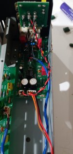
If I've read your instructions correctly (excellent detail by the way!), I should be doing something like this?
So, I just have to adjust the bias (to max 15 mV) on one resistor on each channel, correct? It doesn't matter which one of the 4 on each channel?
Thanks!
If I've read your instructions correctly (excellent detail by the way!), I should be doing something like this?
So, I just have to adjust the bias (to max 15 mV) on one resistor on each channel, correct? It doesn't matter which one of the 4 on each channel?
Thanks!
Attachments
Yes, that hookup is right, and you can use any one of the 4.
Before making any adjustments, you might want to measure the bias on the other 3 resistors on that channel, to see for yourself that they will (should) all give about the same voltage drop across the resistors. Some variations are expected (e.g., the resistors do not have a very tight tolerance), but f they don't give approximately the same voltage drop (±10-15%), something may not be right.
If the unit has not been adjusted since leaving the factory, you will likely see less than 5mV (perhaps as little as 2-3mV). The other posters, particularly ostripper, have indicated 15mV is about optimal for getting the lowest distortion from output transistors, but performance will be at least good anywhere in the range from the factory setting to 15mV. You are probably aware that bias isn't a voltage, but a current, and we use the voltage drop across the emitter resistors as a proxy; you can calculate the actual bias current from Ohms law.
Hi @northpaw
I just wanted to follow up on your last post.
I did check the voltages on the other resistors and they were originally about all the same (2.3mv) before adjustments.
I made the adjustments you suggested, bringing the voltages on each channel to about 15 mV after warm up. I then ran the unit for about an hour at a good volume and powered down.
Brought it back to the bench the next day and let it sit powered on for about 90 minutes without a signal source, and measured the voltages again. They were still around 15 mV. DC offset after the changes rose to about 6.3 mV.
I then ran it again for about another hour. This time I hooked up my WiiM Pro and connected a set of Boston Acoustics CR9's which I have had for several years. Amazing! I can't believe how good this little unit sounds. No distortion, no clipping, even at periods of full volume, and a very nice clean soundstage. Total cost for the unit and caps is about $45!
Right now, I have this set up in my office powering a small pair of Micca MB42's with a Logitech BT adapter as a source, and use it most of the day. I will run it this way for about a week before handing this off to my nephew, and begin recapping the other unit I picked up.
Finally, I wanted to say thank you! Thank you for taking the time to respond to my questions and giving me the confidence to go ahead and proceed with the work. I really appreciate it!
I'm glad it has worked out so well. These units are surprisingly good performers. My thanks go to the earlier posters in this thread who enabled us to get the most out of these amps. I've accumulated 5 of these, 2 260s, 2 275s, and one 260 subwoofer amp, all locally for between $30-$50 and have been delighted with each one.
Your nephew is fortunate to get one of these. Depending on his age and experience, it won't hurt to remind him that the cover vents are not decorative.
Your nephew is fortunate to get one of these. Depending on his age and experience, it won't hurt to remind him that the cover vents are not decorative.
- Home
- Amplifiers
- Solid State
- Sonance Sonamp 260