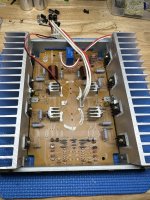
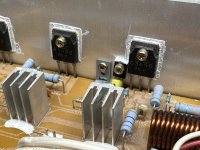
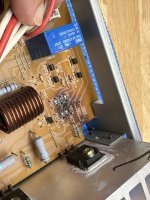
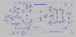
Thanks profiguy. One question to clarify, if I may. Do I want to solder AFTER the resistors 501/401? Is that to attenuate the levels coming in? I assume that removing one pin on the c401/c501 capacitors disconnects the rest of the circuit. Does that mean that the auto-on is disabled? (Guess that's two questions)@mpdevivo - just clip the red and white wires coming from input board and solder white to r501 / red to r401, then remove or lift one pin on both c401 / c501 4.7uf electrolytics. You will also want to use good non polar electrolytics to replace C801 / C901 4.7uf lytics like nichicon muse series and increase their values to at least 22uf for better LF phase linearity and lower cutoff. You could also add some smaller 470nf PP film caps parallel across them.
The Achilles heel of this amp are the main filter caps. They are underrated in voltage and can go bad prematurely. The supply rails are running close to +/- 50V and the caps are rated 50V. I have 2 of these 260 amps for testing speakers and both amps had bulging PS filter caps. I couldn't find 15000uf / 63V versions at the time so I used 10000uf / 63V which were a little taller size but they fit just fine under the cover of the amp. I dont notice any difference in SQ between the 2 cap sizes and also can't measure any more appreciable supply ripple at lower drive impedances. It may be the replacement caps have lower internal R. Either way, these little 260s sound pretty good for cheap bargajn amps. I found them for only 20 bucks each at a thrift store.
I've got the MKII version, and it already has big 15000uf caps in the middle of the main board, so that's good.
I ordered improved op-amps to see if that makes an improvement, but I'll probably go ahead and bypass the whole input board. Oh, I also realized that its easy to bypass the level-setting pots by swapping internal cables. It just switches the Left/right signals.
You want to connect before the resistors since they're a part of the HF lowpass of the turn on board and aren't needed, as the main amp pcb has an input LP on it as well. This is how I run mine with zero stability issues.
Removing the two electrolytics on the input pcb disconnects the turn on circuit.
Make sure your filter caps are rated higher than 50V,. I have the mk2 version as well and it has 50V 15k uf as well.
Removing the two electrolytics on the input pcb disconnects the turn on circuit.
Make sure your filter caps are rated higher than 50V,. I have the mk2 version as well and it has 50V 15k uf as well.
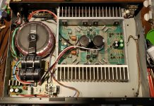
Here's a shot of my 260 test amp...
I made the following changes to it -
I made the following changes to it -
- Removed auto ON circuitry, relay and op amp input buffer pcb
- Bypassed input op amps
- Added conductive plastic pots to inputs for attenuation
- Upgraded all electrolytic caps to Nichicon Muse and Panasonic EB series
- Added extra PS filter caps totalling 20000uf@63v and noise filter chokes with dampening resistors
- Bypassed power relay and wired existing power switch to transformer primary instead with added .047nf/400v arc suppression cap
- increased bias to 5mV across .33R emitter resistors (up from 2.5mV) for lower distortion
Attachments
Last edited:
Wow! Thanks for sharing. I like how you removed the entire input buffer board. I will most likely do that and bypass the left/right level setting pots as I don't need them. The next step you recommended was to replace the C801 / C901 capacitors. The schematic is a little blurry, but it looks like they are specified at 25v, though the components on my board say 63. Should I go with bigger 63v caps just to be safe?Here's a shot of my 260 test amp...
I made the following changes to it -
- Removed auto ON circuitry, relay and op amp input buffer pcb
- Bypassed input op amps
- Added conductive plastic pots to inputs for attenuation
- Upgraded all electrolytic caps to Nichicon Muse and Panasonic EB series
- Added extra PS filter caps totalling 20000uf@63v and noise filter chokes with dampening resistors
- Bypassed power relay and wired existing power switch to transformer primary instead with added .047nf/400v arc suppression cap
- increased bias to 5mV across .33R emitter resistors (up from 2.5mV) for lower distortion
With coupling caps, the higher voltage rating is usually better in terms of dialectric behavior, losses and DF, especially with electrolytics. The other reasoning is having the circuit it couples to running 50V DC rails, so if there's a failure on the amplifier side creating a full rail swing on the coupling cap, it will handle the voltage and safely block it thanks to the higher voltage rating.
I highly recommend increasing C801/901 to about 22uF for better LF linearity. The original 4.7uF cap made the LF start dropping off at 30 Hz. Thats no good in terms of LF linearity if the amp is used for speaker measurement and testing purposes, which is what i use it for. The amp will do close to 100W rms into 8 ohms both channels driven and its dead quiet even with compression drivers - thats a big plus for me. I used to run a LM3886 chip amp for testing but the noise floor wasn't low enough to properly test higher efficiency drivers.
Thee downside to this amp is the small heat sinks, making it dicey to run 4 ohm loads continuously. Some skinny PC fans right above the heatsinks would probably fix that, but for now its just easier to monitor the heatsink temps. It really doesn't sound half bad after the mods compared to some other amps in the $500 - $1000 range.
The bias increase is a must if you want the best distortion performance. My amp was running at about 2.5mV across the emmiter resistors which wasn't enough. 5mV is the sweet spot and it only raises heatsink temps to about 90 deg F at idle. You'll also want to check output offset after adjusting bias. It should be under 30mV.
I tried taking the entire input board out and tapping directly into the RCA jacks like in your example, but without bypassing the power relay that didn't work. I didn't want to muck with the power section, so I put the input board back in and followed your instructions to remove one pin from the 401/501 capacitors. I also replaced the C801/901 with the larger 22uf/50v Muse bipolar caps. Everything works OK, so I put it to work. Still haven't found the time to sit and listen to music on it though!With coupling caps, the higher voltage rating is usually better in terms of dialectric behavior, losses and DF, especially with electrolytics. The other reasoning is having the circuit it couples to running 50V DC rails, so if there's a failure on the amplifier side creating a full rail swing on the coupling cap, it will handle the voltage and safely block it thanks to the higher voltage rating.
I highly recommend increasing C801/901 to about 22uF for better LF linearity. The original 4.7uF cap made the LF start dropping off at 30 Hz. Thats no good in terms of LF linearity if the amp is used for speaker measurement and testing purposes, which is what i use it for. The amp will do close to 100W rms into 8 ohms both channels driven and its dead quiet even with compression drivers - thats a big plus for me. I used to run a LM3886 chip amp for testing but the noise floor wasn't low enough to properly test higher efficiency drivers.
Thee downside to this amp is the small heat sinks, making it dicey to run 4 ohm loads continuously. Some skinny PC fans right above the heatsinks would probably fix that, but for now its just easier to monitor the heatsink temps. It really doesn't sound half bad after the mods compared to some other amps in the $500 - $1000 range.
The bias increase is a must if you want the best distortion performance. My amp was running at about 2.5mV across the emmiter resistors which wasn't enough. 5mV is the sweet spot and it only raises heatsink temps to about 90 deg F at idle. You'll also want to check output offset after adjusting bias. It should be under 30mV.
Attachments
Bypassing the power relay and wiring the power switch to interrupt the mains instead of the 2 DC rails isn't hard.
EDIT - I see your model has a power switch that isnt rated to switch the required AC mains voltage or current. You will need a different power switch for the following modifications. Some earlier models already have the correct rated power switch. Digikey and Mouser both sell switches that fit and are rated for this. I will try to research the correct part number of switch and post it here.
* disclaimer - you're working with AC mains connections and potentially dangerous voltages. Don't try this if you're not familiar working with basic AC mains wiring and switching. I'm not responsible if you hurt yourself, burn down your house or ruin your amp. Always insulate all connections well and double check your work before reconnecting AC mains power. *
Here's what you need to do -
Don't be tempted to reuse the original ceramic suppresion caps at the power switch. That type of cap isn't safety rated for spark suppression on AC mains power switch contacts. If you don't decide to run a suppression cap, the life expectancy of the power switch will be significantly reduced. The suppression cap is considered a safety item, so it should have UL approved markings and a flame resistant coating or casing.
The main reason to bypass the power relay on this amp is the added contact resistance, which just increases further with the relay's age after many cycles of switching DC voltage under load. This will make a noticeable difference in audio quality and eliminate most of the turn on/off noise at speakers.
Hope that all simplifies the whole process for you.
EDIT - I see your model has a power switch that isnt rated to switch the required AC mains voltage or current. You will need a different power switch for the following modifications. Some earlier models already have the correct rated power switch. Digikey and Mouser both sell switches that fit and are rated for this. I will try to research the correct part number of switch and post it here.
* disclaimer - you're working with AC mains connections and potentially dangerous voltages. Don't try this if you're not familiar working with basic AC mains wiring and switching. I'm not responsible if you hurt yourself, burn down your house or ruin your amp. Always insulate all connections well and double check your work before reconnecting AC mains power. *
Here's what you need to do -
- make sure power cord is disconnected from AC mains outlet
- pull apart the connection between the power trans and fuse holder (red and brown wires twisted together)
- disconnect and remove the harness with existing 4 wires leading to power switch along with the 2 ceramic suppression caps
- extend red and brown mains wires and connect to one side of power switch contacts (use heat shrink to insulate all connections)
- add a 47nF/400V suppresion cap across power switch contacts
- jump the switched DC rails at the power relay contacts
- make sure the original heatshrink covering from the power switch assembly is re-attached (important for safety)
Don't be tempted to reuse the original ceramic suppresion caps at the power switch. That type of cap isn't safety rated for spark suppression on AC mains power switch contacts. If you don't decide to run a suppression cap, the life expectancy of the power switch will be significantly reduced. The suppression cap is considered a safety item, so it should have UL approved markings and a flame resistant coating or casing.
The main reason to bypass the power relay on this amp is the added contact resistance, which just increases further with the relay's age after many cycles of switching DC voltage under load. This will make a noticeable difference in audio quality and eliminate most of the turn on/off noise at speakers.
Hope that all simplifies the whole process for you.
Last edited:
Profiguy,Bypassing the power relay and wiring the power switch to interrupt the mains instead of the 2 DC rails isn't hard.
EDIT - I see your model has a power switch that isnt rated to switch the required AC mains voltage or current. You will need a different power switch for the following modifications. Some earlier models already have the correct rated power switch. Digikey and Mouser both sell switches that fit and are rated for this. I will try to research the correct part number of switch and post it here.
* disclaimer - you're working with AC mains connections and potentially dangerous voltages. Don't try this if you're not familiar working with basic AC mains wiring and switching. I'm not responsible if you hurt yourself, burn down your house or ruin your amp. Always insulate all connections well and double check your work before reconnecting AC mains power. *
Here's what you need to do -
- make sure power cord is disconnected from AC mains outlet
- pull apart the connection between the power trans and fuse holder (red and brown wires twisted together)
- disconnect and remove the harness with existing 4 wires leading to power switch along with the 2 ceramic suppression caps
- extend red and brown mains wires and connect to one side of power switch contacts (use heat shrink to insulate all connections)
- add a 47nF/400V suppresion cap across power switch contacts
- jump the switched DC rails at the power relay contacts
- make sure the original heatshrink covering from the power switch assembly is re-attached (important for safety)
Don't be tempted to reuse the original ceramic suppresion caps at the power switch. That type of cap isn't safety rated for spark suppression on AC mains power switch contacts. If you don't decide to run a suppression cap, the life expectancy of the power switch will be significantly reduced. The suppression cap is considered a safety item, so it should have UL approved markings and a flame resistant coating or casing.
The main reason to bypass the power relay on this amp is the added contact resistance, which just increases further with the relay's age after many cycles of switching DC voltage under load. This will make a noticeable difference in audio quality and eliminate most of the turn on/off noise at speakers.
Hope that all simplifies the whole process for you.
It was a while before I logged in and saw your instructions. Honestly, this is a bit advanced for me, and I'm not sure I want to remove the relay. Isn't it there to provide a shutdown in case of a short?
Anyway, I wanted to ask if there would be any benefit to upgrading the relay rather than remove it?
Thanks for your expertise. You've piqued my interest in learning more about power amps!
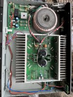
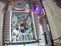
My wife had a Sonamp260 in her work studio playing for many years, we decided it was time for an audio upgrade. The byproduct of this is, I now have an old Sonamp260 that still works fine. What to do?..... Search DIYA for anyone that has tweaked these. BANG, here we are 🙂.
I always felt the input buffer, volume pots and auto-switching circuit held back ultimate performance from this design. My 260 seems a bit older then the ones pictured here, the posted schematics are almost the same but for a few component changes, the main pcb is slightly different as is the psu board. The OS uses Sanken 2SC3856/2SA1492. But the heatsinks are slightly bigger, Yay!
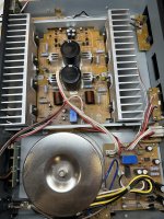
I jumped right in and tried to disable the input buffer section by disconnecting the power connection, header J003A on the PSU board. But now the amp doesn't turn on. The workaround was to re-connect J003A, disconnect signal input to the main board (J005) and connect external RCA's directly to J005 header. This worked fine but the stock input buffer board and circuitry is still being powered for no reason. How can I remove this section and still have the amp turn on as normal?
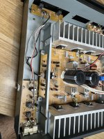
I've also removed all the parts on the main board that will be replace. There is a pcb section that has been getting cooked over the years, higher wattage components lifted from the board will be reinstalled.
Attachments
Luckily I got two of the FR4-green boards.
This is a nice amp. If a make a few changes.
Mine had one fully bad filter cap , every other one was high ESR.
Amazing both amps still worked (even with bad caps).
-Ditch the junk power board and remote start circuit.
-factory set super low 3-5mV bias settings , I set 15-16 mV (50mA per device).
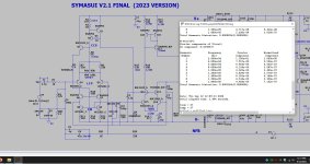
-NFB takeoff point is pulled from one emitter resistor (PCB layout error)_ , takeoff from the output inductors. (yellow wires).
-Replace the lead and lag compensation caps with silver mica 15pF-lead / 270pF - lag
........Thats all on the simulated schema.
-VAS is "starved" (<2mA). change R909,911,912 to 100R. Bias should be turned all the way down. With VAS @ 2.8mA -output (15mV) is
about 12 O'clock on the bias trimmer now.
Slight recompensation - The JUNK ceramic lead was <7pF and the lag 330pF was way off. I replaced with a nice
15pF silver C905. And the lead was replaced with a new silver 270pF. This smoothed the phase margin plot , much better
than the "dodgy caps".
In the end , I am HAPPY !!! These are nice sounding amps , they can drive 80V P-P all day into a 4R load.
My two both lasted over 30 years , NOT ONE bad semi !!!
This design has the "80's" sound like the old Toshiba/Hitachi receivers. It also has native LOW offset , which
is dependent on the quality of the DC blocking cap.
New specs - .02% 20-20Khz , most of the range from 20-15Khz is only .002%. really good for such a simple circuit.
Damn , this amp is DEAD quiet ! Quieter than some of my DIY amps.
OS
Attachments
Last edited:
Update , I finally added the 6 100R VAS resistors. VAS idles at 2.2mA now , gets just a little (barely detectable) warm.
100R is convenient for current readings .48V = 4.8mA .
Loop gain is now 72db with unity gain at 1.6 Mhz.
But , have the bigger lead cap - 15pF. Margin is kept .
Good ! This can be a real nice "starter" project for new members. All through- hole , Keep the protect circuit ,
which I have tripped (id10t)- works real good.
OS
Attachments
Super cool tweaks! Thanks for sharing the details, Pete 🙂
My Sonamp260 sounds much better after the first batch of mods was made. At that time I was on the fence about ditching the original psu but decided not to because I didn't think the amp was worth it. Boy was I wrong, definitely a good foundation for a nice sounding amp after some surgery and mods.
I plan to go back under the hood and mimic the modifications you outlined here.

I did not think I would be happy with such a primitive design. Just 5 devices for the IPS/VAS ?
As a project - -
- using a separate current source for each channel.
-TTA/C004's for VAS , all the rest use ksa/c 120V to-92's.
-Higher Vceo drivers.
- Run at 60V rails.
Then , you would have a straight 120W/8R amp that could really peak out.
45-47V rails give you overkill SOA , why this amp is rated to 2.7R load.
I was surprised they took the NFB feedback WAY from the end of the output trace. Under load , that would add 90% of the
circuit's distortion.
The other distortion mechanism is the low current VAS running the EF2. The Sanken driver/output combo's DO have some of the best
beta for output stages , but 1.5mA is ridiculous ! Another easier way to boost VAS Ic would be to reduce R904 33K--->27K. LTP tail current
would be @.5mA.
The super low .35mA Q901/902 current is why this amp has such low noise.
Great garage or test amp - IMPOSSIBLE to kill this build quality - Ebay has dozens of these for 30-60$ - still ....
Edit - I now have two of these for under 80$ - could not be happier.
OS
Sonance = the most simple version of the "Hitachi topology".
Below is the same topology with advancements.
That beats the "Wolverine" (sub PPM).
Oh yeah - perfect bias for the Sanken A1386/C3519 pairs is lower than the ON's 70-80mA per device.
My HK680 has the same devices , OEM settings are 10mV @ .22R = 45mA per device.
Sonance is 15mV @ .33R , about 47mA (per device)
Attachments
Last edited:
Exactly! Mine powers the outside deck speakers.….Great garage or test amp - IMPOSSIBLE to kill this build quality….
I now have one as my main PC 2.1 system. I did not think this amps fidelity would warrant replacing my main PC
amplifier. But it does , it's actually quieter !
The other is in my dirty parts filled work room.
OS
amplifier. But it does , it's actually quieter !
The other is in my dirty parts filled work room.
OS
Nah .... the 3 channel is a bomb. not enough PS , watts , or Heatsinking.The 3-channel Sonamp version might be perfect for your PC system.
I have the Sonance "virtuoso" sub amp , I gutted it. Put in 50KuF power board , a 40-0-40 300VA trafo and
added a HYPEX uCD400 class D amp to the one big heatsink inside it.
My sub needs 250W+++ to "be itself". uCD puts out about 300W+ with the 300VA + 50KuF combo.
"Virtuoso" is the same enclosure as the 260/260 mk2/260-3. All the same "kit".
OS
Attachments
- Home
- Amplifiers
- Solid State
- Sonance Sonamp 260
