Member
Joined 2003
It's a shame for Scan-Speak...I had a angled voice coil recently with 12mu, quality control issues.
That elliptical voice coil and matching elliptical motor has got to be far more complicated to manufacture than a circular assembly. It is a lot of added complication, and thus added cost. I have read ScanSpeak's material which shows the performance benefits, but I have doubts that the performance is worth the added complexity.

We haven't seen any objective benefits from the measurements of ScanSpeak Ellipticor speakers yet. Indeed, the benefits that come from an ellipticomyth, not from a huge motor.
Nevertheless, they sound very nice.
Nevertheless, they sound very nice.
Member
Joined 2003
Round voice coil, slit revelator cone, lower price, they’ll jump off the shelves 😉
Hi @HiFiCompass, I'm curious why the HFC rating is 2/5 for the Seas A26RE4? Are there some particular things you think are not competitive? Thanks
Nothing special about this driver. The frequency response sucks and the distortion performance is remarkably unremarkable.Hi @HiFiCompass, I'm curious why the HFC rating is 2/5 for the Seas A26RE4? Are there some particular things you think are not competitive? Thanks
Hi,Hi @HiFiCompass, I'm curious why the HFC rating is 2/5 for the Seas A26RE4? Are there some particular things you think are not competitive? Thanks
That woofer has incredible high distortion and far from good a frequency response.
@HiFiCompass
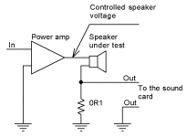
Can you please provide some additional information and preferably a schematic how you do your voice coil current distortion measurements? I thought you had some information on your website, but I can't find it anymore?
I would like to cross-correlate some measurements myself. 🙂
Can you please provide some additional information and preferably a schematic how you do your voice coil current distortion measurements? I thought you had some information on your website, but I can't find it anymore?
I would like to cross-correlate some measurements myself. 🙂
I've never heard the Seas A26RE4, but it's interesting to note that a lot of people like the sound produced by this driver.
From what I understand the A26RE4 was specifically designed to be used without a crossover, effectively having a built in 1st order low pass filter by way of a large inductor resistance in the voice coil so you can crossover at around 2khz to a large tweeter. It also has a very benign cone breakup again facilitating the No-crossover capability. The Inbuilt low pass plus a tweeter that can be high passed with just a capacitor make for a specific sound that some like. So, it was a driver specifically designed to do a job that the majority of modern drivers can’t do and should be used as directed and not for general use imo.
They have a very soft, non-fatiguing sound, which is why many fans of vintage sound like them. But they can't pretend to high quality, high resolution dynamic sound reproduction.I've never heard the Seas A26RE4, but it's interesting to note that a lot of people like the sound produced by this driver.
@HiFiCompass
Can you please provide some additional information and preferably a schematic how you do your voice coil current distortion measurements? I thought you had some information on your website, but I can't find it anymore?
I would like to cross-correlate some measurements myself. 🙂
Attachments
Never a good idea to design a speaker driver like this. SEAS do this a lot and I don't like it at all. What looks to the untrained eye like a well behaved driver in the datasheet due to a smooth rolling off frequency response is actually a potential disaster in terms of non-linear distortion.From what I understand the A26RE4 was specifically designed to be used without a crossover, effectively having a built in 1st order low pass filter by way of a large inductor resistance in the voice coil so you can crossover at around 2khz to a large tweeter. It also has a very benign cone breakup again facilitating the No-crossover capability. The Inbuilt low pass plus a tweeter that can be high passed with just a capacitor make for a specific sound that some like. So, it was a driver specifically designed to do a job that the majority of modern drivers can’t do and should be used as directed and not for general use imo.
With the A26, theoretically the inductance is rolling off the response starting at 5-600Hz or so. Note how the impedance doubles from the minimum of ~7ohm to 14ohm at ~700Hz. Therefore in the absence of cone breakup the response should be down by 6dB at ~700Hz and ~12dB at 2kHz (as the impedance has doubled again) yet the frequency response is flat out to 2kHz. This is because cone breakup is particularly bad from ~800Hz-2kHz and pushes the response back up to flat, after which both the cone and the inductance are each rolling off the response leading to a nominally 2nd order rolloff >2kHz. The presence of cone breakup at 800Hz-2kHz means that 3rd order harmonic distortion will be high over a frequency range that is 1/3rd of that - ~250-700Hz. At 5th order we expect things to look bad from ~150-400Hz. Additionally high order harmonic distortion and intermodulation distortion will be raised when any frequencies above ~800Hz are played due to inductance modulation. We look at the measurements and this is pretty much exactly what we see. To avoid elevated non-linear distortion, we have to avoid using this driver above 150Hz, rendering this driver only useful as a high fidelity subwoofer. Yet it doesn't have suitable xmax for that role either so it's not useful for anything in particular!
It is much better to use a woofer which has an entirely resistive impedance and has a complete lack of cone breakup to well above the highest frequency you wish to use it. The number of 8" woofers in existence that have a complete lack of distortion issues out to to 2kHz can be counted on one hand, let alone 10".
If you're trying to spot a good driver from the datasheet, examine the impedance and the frequency response for this behavior. If the frequency response is flat and the impedance flat over and above the frequency range you wish to use a driver, you might be on to a good performer. If the impedance starts rising due to inductance and the frequency response stays flat (or worse, goes up!), you know to avoid it like the plague.
The exception to this rule is if the motor is incredibly well behaved and produces almost non existent distortion in the first place (e.g. Satori, Scanspeak Revelator) i.e. increasing -80dB components to -60dB isn't nearly as much of an issue as increasing -60dB to -40dB. The only way to know that this is the case is by measuring.
Last edited:
Welcome to the world of marketing and the world were transparent datasheets don't exist.Never a good idea to design a speaker driver like this. SEAS do this a lot and I don't like it at all. What looks to the untrained eye like a well behaved driver in the datasheet due to a smooth rolling off frequency response is actually a potential disaster in terms of non-linear distortion.
With the A26, theoretically the inductance is rolling off the response starting at 5-600Hz or so. Note how the impedance doubles from the minimum of ~7ohm to 14ohm at ~700Hz. Therefore in the absence of cone breakup the response should be down by 6dB at ~700Hz and ~12dB at 2kHz (as the impedance has doubled again) yet the frequency response is flat out to 2kHz. This is because cone breakup is particularly bad from ~800Hz-2kHz and pushes the response back up to flat, after which both the cone and the inductance are each rolling off the response leading to a nominally 2nd order rolloff >2kHz. The presence of cone breakup at 800Hz-2kHz means that 3rd order harmonic distortion will be high over a frequency range that is 1/3rd of that - ~250-700Hz. At 5th order we expect things to look bad from ~150-400Hz. Additionally high order harmonic distortion and intermodulation distortion will be raised when any frequencies above ~800Hz are played due to inductance modulation. We look at the measurements and this is pretty much exactly what we see. To avoid elevated non-linear distortion, we have to avoid using this driver above 150Hz, rendering this driver only useful as a high fidelity subwoofer. Yet it doesn't have suitable xmax for that role either so it's not useful for anything in particular!
It is much better to use a woofer which has an entirely resistive impedance and has a complete lack of cone breakup to well above the highest frequency you wish to use it. The number of 8" woofers in existence that have a complete lack of distortion issues out to to 2kHz can be counted on one hand, let alone 10".
If you're trying to spot a good driver from the datasheet, examine the impedance and the frequency response for this behavior. If the frequency response is flat and the impedance flat over and above the frequency range you wish to use a driver, you might be on to a good performer. If the impedance starts rising due to inductance and the frequency response stays flat (or worse, goes up!), you know to avoid it like the plague.
The exception to this rule is if the motor is incredibly well behaved and produces almost non existent distortion in the first place (e.g. Satori, Scanspeak Revelator) i.e. increasing -80dB components to -60dB isn't nearly as much of an issue as increasing -60dB to -40dB. The only way to know that this is the case is by measuring.
(compared to electronics datasheets, it's a big joke)
Luckily we have people like @HiFiCompass to help us in this big mess 🙂
The gap for the voice coil seems too much. Now I understand why soo much of magnetic force factor is wasted despite of using huge Neo magnets also this is reflecting in the reduced power ratings as cooling will not happen when such large gap.I understand what you say about. No, the problem in both tweeters is in the voice coil rubbing, certainly. I spent a lot of time trying to fix this problem but without success.
The reason is the axis of the elliptical voice coil doesn't match with that of elliptical motor. There is an angle between them about of some degrees.
Moreover, the voice coil edge has a bit of propellerness.
Now why they have kept in the angle is something probably to reduce IMD but no idea.
https://stx.pl/w-22-250-8-fcx.html and many more interesting drivers there at Polish neighbours. Fibreglass 6.5" with copper for 30eur... https://stx.pl/w-18-200-8-fgx.html and many more... Any chance to test some of those?
Buy it, send it, give donation!https://stx.pl/w-22-250-8-fcx.html and many more interesting drivers there at Polish neighbours. Fibreglass 6.5" with copper for 30eur... https://stx.pl/w-18-200-8-fgx.html and many more... Any chance to test some of those?
- Home
- Loudspeakers
- Multi-Way
- Some speaker driver measurements...