🙂It was mostly rhetorical.

But you have learnt something 😀
for sure ... and i have also burnt one finger ... the amp was emitting just a buzz ... and i do not know why but i touched the heatsink ... was unbelievably hot 😱
I understand that some transformers have a fuse inside ? so it could be that just that was down i do not know. However it emitted some smoke ...
So i connected a very power external transformer and than made the board vibrate ... but it did not sweat at all. Just went on pumping current through a short circuit i guess ... what a transformer ... 😱 a 600VA thing
I still have it somewhere ... 🙄
Still related with stability, if you have sensitive ears, like tweaking but don't understand electronics, here is a tweak you can do:
Reduce the compensation cap (e.g. Miller or b-c bypass type, could be different with caps in complex compensation scheme), use styroflex, solder cleanly and shortly. To increase/reduce at small steps I use paralleling with smaller caps. Reducing the compensation cap will have the effect of reducing stability (but default cap is usually oversized to ensure stability and to use common size, such as 100p/82p), so you have to do it slowly while observing the stability issue.
Assuming that you don't have stability problem, reducing the cap will increase the sound quality and up until certain point you will find an 'optimum' value (good trade-off between several quality aspects).
With luck, this alone can turn a 'bad' sounding amp into a great one.
BTW, allow at least half day before trying to perceive 'difference'
thanks a lot i will try to understand this.
I have to say that i exaggerated a little ... i reduce the gain a lot.
The amp in question was a Rotel ra930 ax ...
However i have always had the dream to find a high current low gain amp
i am forced to headphone as i listened to music often during late hours 😱
Therefore i have at hand many headphone amps ... some decent sounding. Problem is that voltage gain is usually too much high to use them as a line stage (it is not uncommon a voltage gain of 10 times ... really too much for any standard power amp)
Even a power buffer (i.e. a power amp with unity gain) should be enough to listen from speakers in my small listening room at moderate level.
I live in a flat with thin walls ... 🙁
A high current power amp with a voltage gain of 3-4 would be really the icing on the cake for me
Fused transformer usually has two inputs: one before the fuse and one after the fuse. If the fuse is blown you have to use the other input/connection. (Fuse is usually 'irreplaceable').I understand that some transformers have a fuse inside ?
Then you have many to choose from in the class-A section (Pass Labs for example).A high current power amp with a voltage gain of 3-4 would be really the icing on the cake for me
Fused transformer usually has two inputs: one before the fuse and one after the fuse. If the fuse is blown you have to use the other input/connection. (Fuse is usually 'irreplaceable').
Thank you very much again. I did not know. Unfortunately i did not stop and i connect another one and that ended the disaster. But at least i have tested the transformer. Even powering a short circuit did not destroy it. 🙄 It must be a very good one

I will have a look immediately. I still prefer AB class ... but i will have a look.Then you have many to choose from in the class-A section (Pass Labs for example)
I was even thinking to the schematic i am attaching
Attachments
IIRC Nelson Pass was once asked to share a design for a good sounding class AB. His response was simply "I don't know how."
Not only rethorical, you started with it in #1!...I do not know if the question is for me...
Parallel to this resistor is a small capacitor, yielding in a maximum frequency response of the feedbeck amplifier to avoid high frequency oscillation. If you lower the resistor, you should have increased the value of the capacitor to keep it on the same turnover frequency. You did not and hf-oscillation occurred running the amp havoc. Meltdown of amp and transformer....to reduce its gain decreasing the feedback resistor value...
The fuse in the transformer is (nearly always) a thermal fuse, eg a soldering and metal spring or alike as a component. Sometimes restorable or replacable.
That's my EMC remark. There is a lot to discuss here, as much as all posts on this forum. Just consider this: every pointing leg of a component outside the board (even when cut off to << 1mm) is an antenna receiving and transmitting. A track is a coil, two parallel tracks a condensator. And so on....The design of lay-out is also important...
The same....which kind of test do you perform to assess the performance of a prototype?...
Involving the last quote: that's what formed my preferences as stated....I want to hear everything of the recording... ...I want to hear the noise of the fingers sliding on strings ... the ambient noise...
There are two things to keep in mind about the recording: the original has been reduced to a flat dimensional stereoscopic reduction, along with ambiance, participants, electronics and what not. It is principally impossible to recreate the exact thing in one's own living room with its own ambiance, participants, electronics and what not. That is adding something to the original (recording) already. If you hear the breathing of the performers on stage and you as present audience, the same thing will differ in your living room. It is depending on a set of qualitive and quantative factors to come close to it. Hence my preferences. And from my experience on the stage, you don't want to hear everything within the recording. There are hardly any unspoiled recordings available.
The are no means, electronically or whatever, to make this possible. Amplification is only possible if something is added, let it be energy and by processing it distortion is unevitable....this is something i cannot easily accept ... if i send inside a signal test of 1 kHz i would like to see only 1kHz at the output ... more or less amplified...
14 bit is more rough, 24 bit is more polished, more analog so to speak....digital with less resolution (like 14 bit) can sound more pleasant than digital with high resolution (24 bit)...More analog...
Remember that you're not equipped with a perfect hearing, let alone your personal interpretation and preferences. There are double blind tests, and these indicates nearly nobody save musicians are able to distingish the differences.
You read AAD on one cd and DDD on another, and you're biased (either way).
That's ok, better even!...I feel immediately if i like or not...
It's one of several candidates that jumped in my mind. There are now some seven designs, not yet decided which to build....interesting ... why not a diamond buffer instead?
Indra1's #84 I do confirm. No matter what measures (means to achieve), switching semiconductors are horrible. Avoid as much possible.
i checked the scheme and no cap in parallelNot only rethorical, you started with it in #1!
Parallel to this resistor is a small capacitor, yielding in a maximum frequency response of the feedbeck amplifier to avoid high frequency oscillation. If you lower the resistor, you should have increased the value of the capacitor to keep it on the same turnover frequency. You did not and hf-oscillation occurred running the amp havoc. Meltdown of amp and transformer
i searched for info about stability analysis but it is beyond me
i guess simulation can provide an answer maybe but again too difficult
the more i read the more i admire designers
i have problem now because i am on tablet
i will continue later
If possible post the circuit drawing here or send the circuit by pm.
Everybody following this thread is curious now.
And believe me, mistakes even made by others are valuable.
I once blew an expensive television set of my employer because I had my oscilloscope on protective earth... and the chassis was not.
Just a distinctive tick. And utter silence. And darkness. The main fuse had tripped.
I found another job.
...learning the hard way😀Just a distinctive tick. And utter silence. And darkness. The main fuse had tripped.
I found another job.
If possible post the circuit drawing here or send the circuit by pm.
Everybody following this thread is curious now.
And believe me, mistakes even made by others are valuable.
I once blew an expensive television set of my employer because I had my oscilloscope on protective earth... and the chassis was not.
Just a distinctive tick. And utter silence. And darkness. The main fuse had tripped.
I found another job.
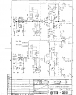
Hi ! if you are referring to me i am attaching the service manual i found on the web. I hope i do not violate any law ... 😱
Schematic is on page 6
i do not remember the exact value but i wanted a voltage gain of 10 in the power stage and i changed the FB resistor accordingly ... amp destroyed 🙁
I wonder if designers prefer to use many amplification stages and then adopt high feedback instead of less amplification stages with low feedback
In my case this will never be my job. My ambitions died at the university ... 🙁 From then on i just copy and paste work of others ...
Attachments
Last edited:
You were right: no capacitor parallel to the feedback resistor!
But there is always stray capacitance, its value depeding on lots of things like length alongside other tracks, route and vias. Let's say only 10pF, then the rolloff starts around 2MHz.
To late of being usefull advice, you had better increased the value of 475E (R611-612) to 1k00 instead of decreasing R635-636, lifting this rolloff to an even higher frequency.
But, way more defining is the 33k2-330p RC load of the voltage amp, yielding in a rolloff of 30kHz! Being within the loopgain, estimated at 26000x or 88dB, havoc can still occur with a closed loop gain of only 18.5x or 25dB.
Other measures in the circuits are the low rolloff (475E-100u) at 3Hz and the input HF just under 1MHz.
Another unusal suspect is the feedback taken from the right side of the fuse, which I consider as the wrong side. If the fuse is blown or not present, the output is driven to maximum values due to the added feedback resistor of 33k2 (R633-634). Any signal present, even a small amount of (hf-) noise can cause the amp to clip from rail to rail.
You can notice that the headphone output is already dampened with 330E resistors, so what was your aim to use the loudspeaker outputs (apart from the reduced gain issue)?
You were right: no capacitor parallel to the feedback resistor! But there is always stray capacitance, its value depeding on lots of things like length alongside other tracks, route and vias. Let's say only 10pF, then the rolloff starts around 2MHz.
To late of being usefull advice, you had better increased the value of 475E (R611-612) to 1k00 instead of decreasing R635-636, lifting this rolloff to an even higher frequency.
Thank you so much for you very kind and extremely precious advice. Never to late at all ... 930ax are all over the market. Actually i think i still have the remains of mine somewhere ... i could try to restore it 🙄
If i understand well you mean that replacing R611 with a 1 kohm resistor the amp will be stable anyway ? this is very important to me.
I have some preamp ideas that all have quite high gain ... from around 5 to 10 times. I have always had issues with power amps because they usually are set to give full power with just 1V ... actually i have one that needs only 0.5V to deliver full power 😱😱😱
Why power amps are designed so sensitive is a real mystery to me.
Please let me elaborate a little. A preamp can be designed to give almost 30V at the output, if not more, with very little THD 😱😱😱 ... one case here below
https://www.stereophile.com/images/315B2110fig3.jpg
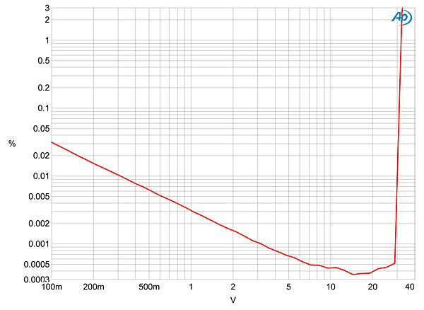
after that just some very little voltage gain and high current is needed to drive most of the speakers in an average listening room.
I mean if i had to design a preamp+amp combination i would put more voltage gain in the preamp for sure ... regulated power supplies ... low noise and distortion ..
In normal conditions i usually cannot turn the volume pot beyond 9 o'clock ...
But, way more defining is the 33k2-330p RC load of the voltage amp, yielding in a rolloff of 30kHz! Being within the loopgain, estimated at 26000x or 88dB, havoc can still occur with a closed loop gain of only 18.5x or 25dB.
Other measures in the circuits are the low rolloff (475E-100u) at 3Hz and the input HF just under 1MHz.
Another unusal suspect is the feedback taken from the right side of the fuse, which I consider as the wrong side.
If the fuse is blown or not present, the output is driven to maximum values due to the added feedback resistor of 33k2 (R633-634).
Any signal present, even a small amount of (hf-) noise can cause the amp to clip from rail to rail.
You can notice that the headphone output is already dampened with 330E resistors, so what was your aim to use the loudspeaker outputs (apart from the reduced gain issue)?
I need to study this more ... i am shocked about the fuse issue ... how they can not think about that ... 🙁
I will study this better ... not easy to understand
As i said i would like to understand if decreasing gain to 5-6 for the power amp section is feasible ...
The fuse i would by-pass immediately.
Thank you very much again.
Last edited:
... Being within the loopgain, estimated at 26000x or 88dB, havoc can still occur with a closed loop gain of only 18.5x or 25dB....
Thanks for the valuable information. I wonder if such a high open loop gain is a good design choice. From some readings i get that a low feedback made possible by lower open loop gains can be desiderable. 🙄
It is less simpler then you think: if you decrease the gain to be able to increase the input signal, the first stage will clip very soon. The 'balance' of all the gains of the stages within the amplifier are more or less deliberate choises. The second stage should do the voltage gain, the last the current gain. The first stage must have some proper gain or you can hear the sea from your speakers... that's noise. (Ntot = N1 + N2/A1 + N3/A1*A2 and so on.)
Given designs from oriental and commercial origin, from that decade, I would not simply change things as an experiment before I had calculate everything thouroughly. All the RC networks has to be set to another local and overal gain. Thus shifting poles and zeros and oscillation lurking. An ommitted feedback cap makes me suspicious: what's the stray value, how's the route. And so on and so on.
If you want an amplifier with low gain, don't start with a high openloop gain amplifier.
How to exchange the gearbox of a sportscar so it will run smooth at strolling pace?
There are simple and very good designs available to build yourself even without much experience. The elaborous designtime and risks has been done by others, and you will have much joy in creating a adequate and good sounding amplifier.
Being a Hiraga-adept myself, I would recommend the various Pass designs with abundant support from other sections on this site. Just post a question there which design would fit your demands and capabilities. Pick one, buy a case and a nice volume attenuator and engage!
That is an odd amplifier design in several ways, not least the rather odd compensation scheme and passive tone controls. Usually I would have expected a miller cap around the Vas transistor to make the integrator well defined, but whatever works I guess.
The lack of any meaningful output device protection rings alarm bells for me as does the lack of any real protection from reactive loads, (No Zobel, no output inductor, no catch diodes, not something I would have been at all comfortable with but it was clearly cheap to make....
If doing the feedback thing (and you probably should), do NOT make the mistake of only using a little, THAT often makes things worse (It turns simple distortion spectra into complex distortion without reducing it by enough to compensate), shovel on as much as you can get away with.
It is less simpler then you think: if you decrease the gain to be able to increase the input signal, the first stage will clip very soon ....
I do not want sound like i am trivializing things ... but said brutally and talking about line stages, a topic very dear to me, i see designs with even 20 active parts per channel and others with just one active part, and with the voltage gain the same ... both are equally fine ? 🙄 and sometimes the simpler ones become classics while the more complex are forgotten ...
so why going for higher complexity ? 😕
And moreover ... i can agree that different routes can lead to a same destination ... but which is the destination ? 😱
Given designs from oriental and commercial origin, from that decade, I would not simply change things as an experiment before I had calculate everything thouroughly.
All the RC networks has to be set to another local and overal gain.
Thus shifting poles and zeros and oscillation lurking.
An ommitted feedback cap makes me suspicious: what's the stray value, how's the route. And so on and so on.
If you want an amplifier with low gain, don't start with a high openloop gain amplifier
thank you for the advice that i understand and with which i agree completely. Therefore can we say that this low wattage amp is not optimal by design ? because they adopt too many stages with high openloop gain and then feedback when only 30W/channel is the target ... or said in another way ... assuming that zero feedback is the nirvana ... the less the feedback the closer to nirvana we are in terms of sounds of course 🙄
And the higher the feedback the farther from nirvana ? or do designs with huge feedback exist that sound impeccably ?
How to exchange the gearbox of a sportscar so it will run smooth at strolling pace?
There are simple and very good designs available to build yourself even without much experience.
The elaborous designtime and risks has been done by others, and you will have much joy in creating a adequate and good sounding amplifier.
Being a Hiraga-adept myself, I would recommend the various Pass designs with abundant support from other sections on this site.
Just post a question there which design would fit your demands and capabilities.
Pick one, buy a case and a nice volume attenuator and engage!
Thanks again but i have to say that i am following the thread about the Pass B1 buffer preamp as well.
I get the feeling that line stages in general and this buffer in particular set the overall sound
I do not want to say that a B1 will make all the power amps sound the same ... but will it ? 😱
This also considering the statement that the 1st watt is the most important.
This is for me a very fundamental question ... also remembering some reviews i read where a same power amp with a different line stage sounded completely different.
Actually it seems to me like all power amps sound at least decent.
Not so line stages.
Last edited:
Why I'm a Hiraga adept:
> extremely simple design
> extremely stable DC settings and flat AC performances
> no bumping output when switching on or off (no protection needed (*))
> sounding nice (most people seem to agree)
> no bias circuit
> in high level class A
> easy to build yourself
> not really difficult components neccessary
But the design is unsurpassed in my view. (No typo here...)
(*) I have my electrostatic loudspeakers connected directly to the outputs.
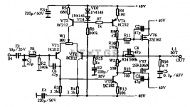
Hi just a comment ... when low wattage is enough i would expect something like the attached schematic ...
From what i understand an amp with a really great midrange
Ok a too basic schematic to be really exciting 😱
Fwiw the amp should be the Aura VA50
Moreover i am pretty sure that the 1st part of the schema (i.e. without the output stage) could be an excellent line stage ...
Impressive +/-48V rails
just a feeling of course
Attachments
Last edited:
Why I'm a Hiraga adept:
Hi ! i thought discussions about religions were not allowed in the forum 😀😉
> extremely simple design
> extremely stable DC settings and flat AC performances
> no bumping output when switching on or off (no protection needed (*))
> sounding nice (most people seem to agree)
> no bias circuit
> in high level class A
> easy to build yourself
> not really difficult components neccessary
But the design is unsurpassed in my view. (No typo here...)
(*) I have my electrostatic loudspeakers connected directly to the outputs.
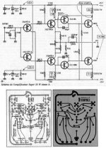
Hi thank you very much indeed for the valuable advice.
Just to be sure ... is it the one attached ?
I have a question ... reducing the bias has a really big impact on the sound ?
It is the only thing that i do not like much ... high bias
Are you aware of kit/pcb for diyers ?
Thanks a lot for the very interesting suggestion 🙂
Attachments
For some combination, but not all.... I get the feeling that line stages in general and this buffer in particular set the overall sound ...
There are plenty of good and bad designs for both.... Actually it seems to me like all power amps sound at least decent.
Not so line stages.
When reading about others describing sonic impression, pay very close attention to the type of speakers being used.
Low bias is less of a problem for low efficiency speakers. High eff. speakers need low voltage but sounds best at high current bias.... It is the only thing that i do not like much ... high bias ...
Last edited:
For some combination, but not all.
There are plenty of good and bad designs for both.
Hi ! yes but i read something about the 1st watt being decisive for sound.
1st Watt = 2.83V on 8 ohm ...
Moreover i read about the Voltage Amplification Stage setting the sound.
I tend to believe in the second statement ... that VAS is very important for the overall sound.
A VAS can provide all the voltage gain needed
I would love to see power amps that act only as a current gain stages with different currents of course (i.e. high current buffers).
From what i understand some power amps were designed just like that and sounded phenomenal like the old Harman Kardon Citation XX
When reading about others describing sonic impression, pay very close attention to the type of speakers being used. Low bias is less of a problem for low efficiency speakers. High eff. speakers need low voltage but sounds best at high current bias
i did not think about it It is very true indeed
Actually high eff speakers can show very well the sonic advantages of class A operations and maybe confirm the 1st watt theory ?
They must be very revealing indeed ... and so higher in quality in the end.
Attachments

Last edited:
- Home
- General Interest
- Everything Else
- Some questions about the process of designing audio circuits