I have some 2SJ103GR. Their IDSS fell in the 3-4mA range, if I remember correctly. Can they be used for Q3 in the DAO-TCS even though their IDSS is too low?
No, best to use 2SA970BL in the latest version at the DAO SE thread.
Or use 2SJ74GR cacscoded by 2SJ103GR.
Much more updated information there.
Take time to read before proceeding.
Patrick
Or use 2SJ74GR cacscoded by 2SJ103GR.
Much more updated information there.
Take time to read before proceeding.
Patrick
😕
The DAO SE thread in the headphones section? I have read it twice more and see absolutely no reference to 2SA970BL. The only version of the schematic I saw in the thread which featured the TCS used 2SJ74.
Guess I will reread this thread, too....
Edit: Maybe I called it by the wrong name. The JFET in question is Q3 in the simplified schematics, but may e Q5 in the DAO schematics. Found some information on TubeCad.
Last edited:
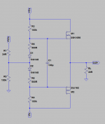
Most probably nothing new, but I could not find something similar on the net.
Biased at slightly negative tempco, the output impedance is reasonable at ~3R.
No use for speakers, but more than sufficient for headphones.
The 2nd harmonics can be lower by proper Yfs & Vgs matching.
And the low Vgs means it eats up very little voltage headroom.
Wonder why no one uses these power laterals for phones ......
🙂
Patrick
PS Only simulated. Not tested. Build at own risk.
.
Attachments
EUVL,
This is really nice - I have never seen it either. I will try out as soon as I get home from trip abroad. I was wondering if there is any issue with "crossover" distortion due to 0.6v turn on voltage of 4148's? Or maybe doesn't matter since they are always on and flowing already sort of like class A diode switch.
Thanks for sharing this very clever design.
X
Btw, assuming 15v rails what is quiescent bias current? Also there is no gain right? Just a current follower.
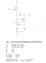
I've used them on phones, but why not a single ended source follower.
You don't really need the high current output or efficiency of a push pull circuit for headphones.
You don't really need the high current output or efficiency of a push pull circuit for headphones.
> but why not a single ended source follower.
Lower even harmonics.
Personal preference.
Patrick
Lower even harmonics.
Personal preference.
Patrick
> but why not a single ended source follower.
Personal preference.
Patrick

Last edited:
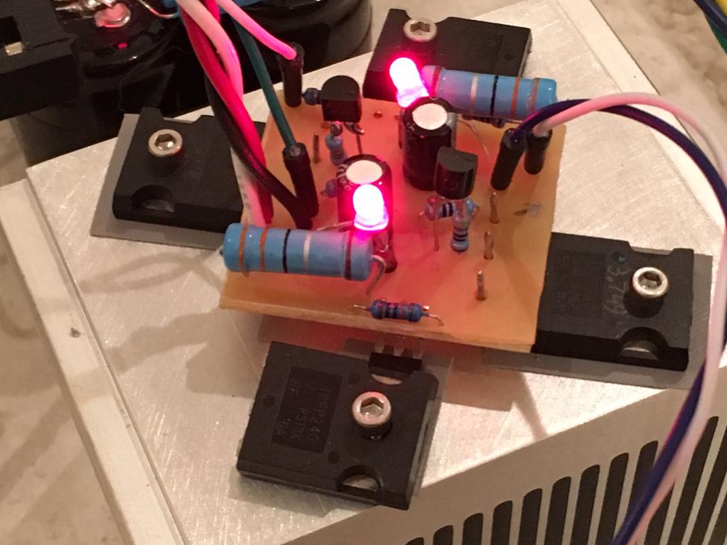
I have built one more DAO, this time with the Taylor mod, and it sounds great indeed. The Taylor mod added a bit more transparancy, which is now approaching electrostatic territory.
The best I heard yet with dynamic headphones.
The difference from the original DAO is subtle, which is not surprising since it is allready a very good headphoneamp. The one with the Taylor is just that tad better though, so it is absolutely worthwhile to implement the Taylor mod.
Overall it sounds very organic and natural with clear clean highs and deep firm low's. No sign of listening fatigue at any volume level, even for long listening periods. It also has the music in a firm grip at all times, even at high levels and massive music it never gets muddy in the sound. I can easily live with this headphoneamp😉 Attached is a pic of the test setup, with the Taylor hanging in the lower right corner of each board. The supply is a shared 160VA 2x18V donut, with 40.000uF and 1,8mH in a CLC config for each channel. It is dead quiet without signal.
Thanks a lot for sharing, Patrick.
🙂
Hi Steen,
What is the Taylor mod? Looked for it without success. I have similar looking amp and will be boxing it up soon. Using 100VA 15v toroidal and 33mF//0.25R//33mF CRC. Those IRFP's where the LU1014's are simple dead MOSFET bodies being used as clamps. I am using combination Zener and LED to get the correct voltage for the games. J310 and 470R is used as constant current source.
What impedance headphones are you driving? Wondering if this amp is more for low impedance 30 to 60ohm vs 250ohm headphones?
Thanks EUVL for the nice design.
Last edited:
See here for general details on the Taylor source follower. In short, it uses an extra couple resistors and a transistor to turn the single-ended buffer into a push-pull buffer which can perform better into lower impedance loads (although, some extra distortion is also introduced). If you look through the DAO thread in the headphones section, you will find five different PDFs about various changes and updates to the DAO circuit. I believe the "Part 2b" PDF discusses the Taylor current source version.
See here for general details on the Taylor source follower. In short, it uses an extra couple resistors and a transistor to turn the single-ended buffer into a push-pull buffer which can perform better into lower impedance loads (although, some extra distortion is also introduced). If you look through the DAO thread in the headphones section, you will find five different PDFs about various changes and updates to the DAO circuit. I believe the "Part 2b" PDF discusses the Taylor current source version.
Thanks for the link and clarification. In very practical terms - how would I implement it on the DAO circuit with LU1014 and IRFP240?
Someone asked by PM about updated schematics with SMD JFETs.
While BF862 ans 2SK209 N-JFETs are still available, there is simply no replacement for 2SJ74.
So I am afraid that the only solution is to use a PNP bipolar instead.
Just as we did with the DAO SE, for slightly different (max. voltage) reasons.
The DAO SE all-FET Class-A ZGF Headphone Amplifier
See also :
https://www.tubecad.com/2004/blog0023.htm
Thank you for your interest,
Patrick
If you can find 2SJ74, I am sure you can still find 2SK170.
For max voltage of BF862 vs. 2SK170, refer to datasheet.
Patrick
For max voltage of BF862 vs. 2SK170, refer to datasheet.
Patrick
Really appreciate Patrick. Can I use 2SK209GR instead of BL? BL versions are not available to purchase in small numbers at mouser or digikey.
Maybe should consider a GB :
2SK209-BL(TE85L,F) Toshiba | Transistor | Other transistors - chip1stop.com)
Patrick
2SK209-BL(TE85L,F) Toshiba | Transistor | Other transistors - chip1stop.com)
Patrick
- Home
- Amplifiers
- Pass Labs
- Some other Source Follower Configurations