Yes, agree. That amp happened to require a higher voltage in that location than a single bipolar-transistor-based device provides.I believe he's trying to describe the circuit used by Mark Alexander in his current-feedback power amplifier - linked from post #127. See Figure 3 (pg 6) of the Application Note, and the discussion in the last third of pg 5.
Dale
@gerhard:
hmmm.. I also noticed the picture of a mist-covered landscape - felt fine and attractively quiet and relaxed ;-)
That was in the middle of December, a nice warm day when it should freeze.
I took the opportunity for a day-long motorbike ride on the Suebian Alb and returned
home in the evening through the valley of the Blau river. The Blau spring is in
Blaubeuren, and it flows into the Danube only 25 km downstream in Ulm. I really
love that valley, lived in the hood for some years.
regards, Gerhard
I should have paid closer attention to the focus; it is really sharp only on the left side.
Last edited:
@gerhard
Hi again ... just noticed that you had replied to my comment about the picture - I don't remember getting a diyaudio email about the reply so I haven't seen it until now ...
Taking a look at Google maps it looks as if Blaubeuren is not so long from Tübingen which is where one side of my family comes from ... Going about a 100 years back in time my grand-grandfather left Germany to avoid being involved in WW1 (maybe that has led to my existence today?) and moved to a city just about 100 kms from the German border. I actually hope to visit Tübingen in a not too distant future - just to get an impression of what this area - and people here - may be like. To that end, looking at your picture and reading your text, it looks very attractive landscape-wise ... And, yes, I do notice the slight blurring of the photo on the right side ... yet IMHO still a so quiet and fine atmosphere ;-)
Cheers, Jesper
That was in the middle of December, a nice warm day when it should freeze.
I took the opportunity for a day-long motorbike ride on the Suebian Alb and returned
home in the evening through the valley of the Blau river. The Blau spring is in
Blaubeuren, and it flows into the Danube only 25 km downstream in Ulm. I really
love that valley, lived in the hood for some years.
regards, Gerhard
I should have paid closer attention to the focus; it is really sharp only on the left side.
Hi again ... just noticed that you had replied to my comment about the picture - I don't remember getting a diyaudio email about the reply so I haven't seen it until now ...
Taking a look at Google maps it looks as if Blaubeuren is not so long from Tübingen which is where one side of my family comes from ... Going about a 100 years back in time my grand-grandfather left Germany to avoid being involved in WW1 (maybe that has led to my existence today?) and moved to a city just about 100 kms from the German border. I actually hope to visit Tübingen in a not too distant future - just to get an impression of what this area - and people here - may be like. To that end, looking at your picture and reading your text, it looks very attractive landscape-wise ... And, yes, I do notice the slight blurring of the photo on the right side ... yet IMHO still a so quiet and fine atmosphere ;-)
Cheers, Jesper
@wrenchone ..
Hi ... did you by any chance do some noise measurements (FFT) on this?
Cheers,
Jesper
I like using reverse biased transistor bases as zeners - it takes very little current to get a solid reference, unlike conventional zener diodes of the same voltage range.Voltage is somewhere between 7.5 to 8V. The earliest I saw this was in a magazine back in the 70's, using the B-E junction of a 2N3638.The article touted them as a good, sharp low current reference. 2N3904s work ok for this. I haven't done a comparison between various transistor types in this application. This might prove instructive.
Hi ... did you by any chance do some noise measurements (FFT) on this?
Cheers,
Jesper
Nope - I generally use them where zener current, rather than noise is an issue. For low noise applications, I used GaAsP or GaP LEDs, or in some cases, a 30V zener with a bypass capacitor, sized in accordance to the zener impedance.
Hi wrenchone,
Thanks for your feedback ... will remember the transistor option in case I have a need for low current stabilization.
Cheers,
Jesper
Nope - I generally use them where zener current, rather than noise is an issue. For low noise applications, I used GaAsP or GaP LEDs, or in some cases, a 30V zener with a bypass capacitor, sized in accordance to the zener impedance.
Thanks for your feedback ... will remember the transistor option in case I have a need for low current stabilization.
Cheers,
Jesper
One thing we might want to do is calculate a "signal-to-noise ratio" for these various references, namely the given voltage divided by the total noise in a specified bandwidth.
Also, I noticed the other day while doing some work for a client that there are more zeners for lower current operation than I'd seen before. I have no idea about their noise properties.
Also, I noticed the other day while doing some work for a client that there are more zeners for lower current operation than I'd seen before. I have no idea about their noise properties.
An option to remember is to stack LEDs, where the noise contribution will add up as sqrt👎, rather than using a single LED and multiplying it and its noise by n.
I am currently measuring some other LEDs from my junk box to
get some more variation to the mix.
Noise add geometrically, or how it is called. That is if you have
n noise voltages v1,..,vn you get the total noise as
sqrt(v1^2+..+vn^2)
I use batteries and as can be seen from the schematic
each op amp as well as the current sources for the DUT
have a series resistance of 10 Ohms on the supply line
and is decoupled with 100uF in parallel w. 10nF. Further,
I took care to have a separate ground lead for the op
amp decoupling to separate this from the low-level ground.
As you can see from the idle measurements, the measured
noise coincides well with the calculated theoretical noise.
The major error factors here are the unknown bandwidth
of the soundcard input filter and that I calibrate the program
using my scope which has never been calibrated in over
25 years (the point of the experiment wasn't to get any
exact absolute figures anyway, but try to understand the
relative performance of various diodes.) I should add that
I could not see any hint of hum on the scope for any of
the measurements, except if attaching the DVM to the DUT.
Hence, I could not measure voltage drop while measuring
noise.
I am interested to see the noise spectrum of the LED and Zener 12V. Please send the snapshots if one can do the FFT of them.
I am interested to see the noise spectrum of the LED and Zener 12V. Please send the snapshots if one can do the FFT of them.
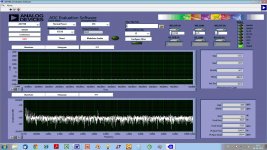
Hi ... here's one on the EL204YD (made with AD7760 evaluation board). The LF spectrum in my measurement setup has a bit more noise than the upper frequencies - thus the LF noise spectrum probably is better than shown. The ~3 kHz spike is an artifact (other noise). Current is 5.7 mA.
In my experience Zeners vary A LOT (can be up to about 45 dBs difference) in their noise spectrum depending on zener voltage and manufacturer - I always measure the specific zener to see what the noise is like.
Best regards,
Jesper
Attachments
Highlights
Could you specify some some highlights in terms of manufacturer and zener voltage?
Thanks
Could you specify some some highlights in terms of manufacturer and zener voltage?
Thanks
Hi ... here's one on the EL204YD (made with AD7760 evaluation board). The LF spectrum in my measurement setup has a bit more noise than the upper frequencies - thus the LF noise spectrum probably is better than shown. The ~3 kHz spike is an artifact (other noise). Current is 5.7 mA.
In my experience Zeners vary A LOT (can be up to about 45 dBs difference) in their noise spectrum depending on zener voltage and manufacturer - I always measure the specific zener to see what the noise is like.
Best regards,
Jesper
Can you do the same analysis to the zener 12V that you have pls specify the name of the manufacturer if you have?
@Piersma:
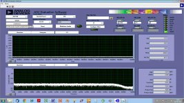
No, not really ... I in general use BZX79 types from NXP - mostly because Samuel Groner suggests them on his website due to their tight voltage specifications. However, I've found two diodes that are very low noise (very close to a low-noise LED). Those are 6.8 VDC BZX79s from NXP (lowest noise - around - 150 dB ref. 3.6 VDC, FFT attached) and a 10 VDC BZX79, again from NXP. This one in general has a 5-6 dB higher noise floor than the 6.8 VDC type. But please note that I've not made extensive measurements of zeners - I don't use them that much so have just measured what I needed to know about.
@rhythmsandy:
Cheers,
Jesper
Could you specify some some highlights in terms of manufacturer and zener voltage?
Thanks
No, not really ... I in general use BZX79 types from NXP - mostly because Samuel Groner suggests them on his website due to their tight voltage specifications. However, I've found two diodes that are very low noise (very close to a low-noise LED). Those are 6.8 VDC BZX79s from NXP (lowest noise - around - 150 dB ref. 3.6 VDC, FFT attached) and a 10 VDC BZX79, again from NXP. This one in general has a 5-6 dB higher noise floor than the 6.8 VDC type. But please note that I've not made extensive measurements of zeners - I don't use them that much so have just measured what I needed to know about.
@rhythmsandy:
No, I'm sorry - the 12 VDC zener I have is very noisy. You can't use e.g. two 6.8 VDC types or the 10 VDC type mentioned above?Can you do the same analysis to the zener 12V that you have pls specify the name of the manufacturer if you have?
Cheers,
Jesper
Attachments
Last edited:
The datasheet for the LM336-5.0 shows 400 nanovolts (.4 uv) at 10hz decreasing to 200 nanovolts (.2uv) at 1khz. Christer's test showed LEDs in the region of .2 to .4uv. This seems to show the LM 336 is in the same noise region as LEDs or am I reading something wrong ?
http://www.ti.com.cn/cn/lit/ds/symlink/lm136-5.0.pdf
http://www.ti.com.cn/cn/lit/ds/symlink/lm136-5.0.pdf
Last edited:
Someone just the other day pointed me to a TI regulator as the best he'd seen. Before even pulling up the datasheet I said That sounds like noise spectral density, not total noise. Sadly (except for the satisfaction of vindication), it was.Don't mix noise with noise density.
Consider PSRR when evaluating low noise regulators
The ADM7150, 7151, 7156, 7157, ADP7158, and 7159 have extremely low noise spectral density (<1.7nV/rt-Hz) and low total noise (<1.6uVrms) from 10Hz to 100KHz. The 1/f noise corner can be tweaked by adjusting a single capacitor.
I no longer work for Analog Devices but I was involved in the design and evaluation of ADM7150 and ADM7151. The ADM7156, ADM7157, ADP7158, and APD7159 are higher output current versions of the 50/51 and share the same architecture. These regulators use bandgap references instead of zeners because their temperature stability and absolute voltage can be precisely trimmed during manufacturing.
One factor most people seem to ignore is the impact that the Power Supply Rejection Ratio (PSRR) of a regulator has on the total output noise. For example, assume that a regulator has an output noise spectral density specification of about 3 nV/rt-Hz at 1kHz. If there is only 100uV noise at 1 kHz on the power supply rail and the regulator PSRR is 60dB at 1kHz, 100 nV of noise will appear at the output. This is 33x greater than the internally generated noise. In order to attenuate the input noise to levels lower than the internal generated noise the regulator must have a PSRR of at least 90dB in this example. The ADM715x and ADP175x families combined extremely low internally generated noise with extremely high PSRR to achieve truly ultra-low noise performance.
Careful attention to the layout around the regulators is also important as noise can also be magnetically coupled into the circuit. For example, a noise voltage of 1nV can be generated by a current of 1uA coupling into a 1 mill-ohm circuit trace. Keeping all AC power traces and transformers well away from the regulator is vital to eliminating magnetically coupled noise. In some critical applications, a Faraday cage and or mu-metal shielding may also be necessary.
can you tell us how to measure 1 nano volt of noise? what is the procedure and what equipment and atmosphere is actually required?
can you tell us how to measure 1 nano volt of noise? what is the procedure and what equipment and atmosphere is actually required?
Measuring noise at the 1nV/rt-Hz level is not for the faint of heart or amateur level enthusiast. First of all, one needs to have access to some very specialized and expensive lab equipment. Secondly, one needs to have access to some very expensive components, we’re talking $35 JFETs and $20 capacitors. And thirdly, one needs to have a thorough understanding of all the factors that can affect the measurements and the patience of Job to make it all work.
I was able to convince my management to spend about $100K on a phase noise analyzer with a noise floor of about 1nV/rt-Hz. The Agilent E5505A is able to directly measure noise from 0.01Hz to well over a gigahertz. Even though the noise floor of the E5505A was extremely low, it was on the order of the noise level I was trying to measure.
In order to keep the noise of the E5505A from contributing more that 1% to the total noise, I needed to amplify the output noise of the regulators under test at least 20dB without adding too much noise in the process. I was able to design and build a high gain (44dB), wideband (1Hz to 10MHz), ultra-low noise preamp with an input referred noise of about 300pV/rt-Hz. This meant that the preamp contributed an additional 10% to the total noise. To prevent noise from entering the measurement through the preamp power supply, I had to also design and build a power supply whose output noise was less than 10uV rms from 10Hz to 10MHz.
Making the noise measurement itself required averaging up to 20 “runs” and manually removing environmental artifacts from the data. Each run took between 90 minutes to two hours to complete. After the runs were done, it was a simple matter to process them all through an Excel macro to generate the spectral noise density plot over the 1Hz to 10MHz frequency range. It typically took well over 5 hours for “quick” measurement and 20 hours for a plot suitable for the datasheet
so which Jfets in specific?
- Home
- Design & Build
- Parts
- Some noise measurements for LEDs and zener diodes