hugobors said:Hello
What's the best way to make a low noise adjustable current source.
In fact I'm looking for a low noise adjustable voltage source to drive a mosfet gate.
I've tried 9V1 zener diode paralleled by a 10K multiturn adjustable, but what a noise.......
Do you have some ideas?
LED, TL431?
Thanks
What MOSFET transistor is it?
Is it in the output stage of a power amplifier?
TL431 might be a good option.
Because you can change voltage of TL431 using a trim potentiometer.
s it in the output stage of a power amplifier?
No it's the current source of a preamplifier with IRF9610 as current source.
TL431 might be a good option.
Because you can change voltage of TL431 using a trim potentiometer.
Isn't the TL431 too noisy for this application?
I've tried something that work well but I don't have the tools to measure it. It's a 2SK30 mounted in current source (gate directly connected to source) feeding a trim pot.
Simple, adjustable and seems to be low noise (in my shematic and with a stax for listening test)
Thanks
Simple, adjustable and seems to be low noise (in my shematic and with a stax for listening test)
Thanks
jwb said:Not sure why you would measure the noise bandwidth over such a wide band. Surely a voltage reference has a bandwidth of interest only at DC. Normally you would put a capacitor across the reference to reduce the bandwidth to some tiny amount as has already been noted in this thread.
Noise = probability that the reference voltage isn't what you expect it to be. For a reference you have to look at it over time to estimate the "confidence" of a measurement.
You can do the math involving the sampling rate and probability distribution function.
Want a really low noise reference ? -- put a low noise integrator after the device, not "just" a capacitor. When you simply put an RC filter on a reference, then connect to an opamp the input bias current causes an offset error.
Great work, Christer! How about different color leds from the same family of devices? Did I miss this in reading this thread? You have a great test rig. Just plug in a red, yellow and green one at two ma, and compare. You will have my appreciation, (to save me from doing this). 😉
John, you may want to do it anyway. Christer mentioned that he hadn't really determined the relative noise contribution of the current source versus the LED (BTW, major props to Christer for both the measurements and his directness about possible limitations and errors!). Now, his measurements may be correct, but I'd like to see some confirmation with a different test setup- after all, don't you think it's odd (albeit interesting) that there's a minimum to the noise at a current well below where the impedance of the LED is at a minimum?
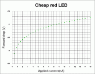
I'm attaching a Vf versus current graph of a cheap red LED, courtesy of Morgan Jones. I've done some single point measurements which give me very similar results. Naively, you'd think that there would be lower noise at 10mA than 3mA since the dynamic impedance is lower. If indeed the minimum is real and not a measurement artifact, that's a VERY interesting result.
When I get back to the US later this month, if you've got time, are you interested in trying a couple of experiments?
Attachments
I post here again
link to Christer latest version of noise test figures.
It is a valuable and useful paper.
It gives some hints of level of noise in voltage references we commonly use.
Like Zener diodes, 1N4148, TL431, different colour LEDs and small signal transistors.
Very useful!
I see such an experienced man as John Curl can see the value in
this good work done by Christer.
Christer Noise Test Paper 1.4
🙂
it would be helpful to baseline the measurements -- short the input of the LM1115 and measure for 10s.
one way to determine the noise would be to take a very low level , very pure sine wave signal, amplify it and then use the averaging function to determine how many averaging periods are necessary to return it to a pure sine wave. Bonnie discussed this in EDN from a different angle in the most recent issue.
now if I can get my son who just took stochastic calculus to come up with the math we are all done 🙂
Well, it seems that I have used the noisiest possible zeners for my Class-D prototype input stage opamps: 6v8 zeners, biased at 5mA (showing 13uV noise) 🙁
They are connected to the base of a NPN transistor (PNP for the negative rail), with a series collector resistor to share dissipation, to regulate the supply rails to the required +/-6.3V, and the zeners themselves are bypased by a 100nF ceramic cap.
Should I expect to improve the audio output noise floor noticeable if I use a lower noise zener configuration (such as 5V6, that shows 2.9uV noise)?
Thanks!
john curl said:Great work, Christer! How about different color leds from the same family of devices? Did I miss this in reading this thread? You have a great test rig. Just plug in a red, yellow and green one at two ma, and compare. You will have my appreciation, (to save me from doing this). 😉
Sorry for not answering earlier John. I have been away from the forum for some time.
I did deliberately try to use the whole spectrum of colours from the same LED family, in this case the Everlight EL204 series. One exception was the 697 nm red, where I used EL202 instead. I don't quite remember why, but probably the 204 version was out of stock when I bought the LEDs. Anyway, this means I tried the EL204 all the way from reddish orange up to blue. I also used the IR204 IR LED, but I am not so sure if that one has much relation to the EL204 series. In addition to these I threw in some other LEDs for comparison. I tried some EL1254, which were a bit noisier than the corresponding EL204 ones. I also tried a red LED of a different brand, Kingbright, which had approximately the same noise figures as thered EL202. Since the EL202/204 and EL1254 have approximately the same max If and it seems that noise is not only correlated to wavelength and max current. This obviously means one cannot just take my figures and hope they are the same for all LEDs. You definitely whoudl make your own measurements with the devices you use. The test rig is very simple but surprisingly good, and I am sure you could easily come up with something better.
I never thought the day would come when you would learn something about electronics from me, especially not empirical knowledge. 🙂
Pierre,
If you have no problem with the noise, just stay with what you have. Otherwise, three LEDs in series would probably give about the best result possible. Please see post #77 (although theses figures are probably not quite correct as I remarked on later).
If you have no problem with the noise, just stay with what you have. Otherwise, three LEDs in series would probably give about the best result possible. Please see post #77 (although theses figures are probably not quite correct as I remarked on later).
jackinnj said:it would be helpful to baseline the measurements -- short the input of the LM1115 and measure for 10s.
I did exactly that, as I pointed out in the paper. The result was 0.19 uV, which as far as I can remember turned out to coincide very well with the theoretically expeccted value.
Hi,
knowledge surprises everyone, especially if it creeps up from behind.
Keep up the good (empirical) work.
knowledge surprises everyone, especially if it creeps up from behind.
Keep up the good (empirical) work.
An alternative?
I've been following the thread on and off for a while and commend the work so far.
Can I suggest that we add some measurements from CLD (current limiting diode) based circuits?
Just off the top of my head I'm thinking these might be quieter than Bipolar alternatives due to the noise mechanisms involved - i.e. the lower number of material interfaces within the devices (two ohmic for CLDs as opposed to two ohmic and two p-n for bipolar devices).
I might be way off the mark, but still free samples are available here:
http://www.centralsemi.com/samples.aspx
So it might be worth a try?
Re: An alternative?
Sure, feel free to do it. I have posted the schematic of the test rig. 😉
I had to google to see what a CLD is, but it seems to be another name for the constant-current diode, which, as I understand it, is just an ordinary JFET CCS, packaged as a diode and labelled depending on the IDSS it has. So I guess one could just use a low-noise JFET instead and connect as a CCS. I assume however that you intend to use it as replacement for the BJT-based CCS in the test rig, since it won't work as a voltage ref. This is actually one of the things I have considered if ever making a round 2 of these experiments.
annex666 said:
Can I suggest that we add some measurements from CLD (current limiting diode) based circuits?
Just off the top of my head I'm thinking these might be quieter than Bipolar alternatives due to the noise mechanisms involved - i.e. the lower number of material interfaces within the devices (two ohmic for CLDs as opposed to two ohmic and two p-n for bipolar devices).
Sure, feel free to do it. I have posted the schematic of the test rig. 😉
I had to google to see what a CLD is, but it seems to be another name for the constant-current diode, which, as I understand it, is just an ordinary JFET CCS, packaged as a diode and labelled depending on the IDSS it has. So I guess one could just use a low-noise JFET instead and connect as a CCS. I assume however that you intend to use it as replacement for the BJT-based CCS in the test rig, since it won't work as a voltage ref. This is actually one of the things I have considered if ever making a round 2 of these experiments.
You're right about the fundamental operation of the CLD/CCD/self-biased-JFET/... I thought I'd mention it as they are available pre-trimmed and potentially simplify a lot of the commonly used circuits.
I'm afraid I don't have the required measurement equipment as I've just finished university and no longer have access to a lab (something I will have to rectify at some point...) so I can't make the measurements myself, but hopefully some kind fellow subscribing to the thread will pick up on the suggestion.
...and yes, I was considering it in combination with a resistor as a voltage reference 😉
annex666 said:You're right about the fundamental operation of the CLD/CCD/self-biased-JFET/... I thought I'd mention it as they are available pre-trimmed and potentially simplify a lot of the commonly used circuits.
Yes, but they are usully very imprecise and require a high voltage drop etc., and they are hardly made to be low noise. I have a few of those and they are almost useless since the tolerance on the current is so bad. An 2SK170 running at IDSS or maybe with a small resistor is almost as simple, and probably much better.
I'm afraid I don't have the required measurement equipment as I've just finished university and no longer have access to a lab (something I will have to rectify at some point...) so I can't make the measurements myself, but hopefully some kind fellow subscribing to the thread will pick up on the suggestion.
It basically takes the components, a protoboard and a PC with a soundcard. The only thing I used the scope for was to measure a sine wave I used to calibrate the level of the soundcard in the measurement program. I guess a voltmeter might be good enough to do that. We are not talking precise absolute figures here, but primarily comparing different components to each other.
...and yes, I was considering it in combination with a resistor as a voltage reference 😉
OK, well some use that too in circuits. Maybe it is even just as good as many other voltage reference to give a stable voltage. As for noise, it might perhaps be a good alternative if the resistor is small enough.
1N823
By chance I found that the noise of an 1N823 (6.2V temperature compensated) is dramatically less than that of ordinary zeners, even when you need more than one for getting the required voltage.
Cheers,
Gerhard
By chance I found that the noise of an 1N823 (6.2V temperature compensated) is dramatically less than that of ordinary zeners, even when you need more than one for getting the required voltage.
Cheers,
Gerhard
john curl said:Great work, Christer!
How about different color leds from the same family of devices?
Did I miss this in reading this thread?
You have a great test rig. Just plug in a red, yellow and green one at two ma, and compare.
You will have my appreciation, (to save me from doing this). 😉
Hello, all serious noise level 'care-about-diyaudio-builders'
it is time for a
Mister John Curl BUMP
as you probably wouldnt be very much impressed
by
a lineup bump
Your own fault - you may be missing something!
😎
no harm to john curl - he has shown me some good things
I have learnt a lot from
Thanks John!
I never forget.
- Home
- Design & Build
- Parts
- Some noise measurements for LEDs and zener diodes