Not a dumb question at all!Used as a cathode load for a triode common cathode voltage amplifier, wouldn't the 'best' device be the one that gives you the most constant (and a usable) Vf over the widest range of Ip through the tube? In that case, using a red LED at Ip > or = 5mA should work pretty well... No?
What is the parameter we actually want to be stable: the grid-cathode voltage (Vgk), or the anode current (Ia)?
Suppose we have a 12AX7 stage running from a B+ of 300 volts DC, biased to 1 ma of cathode current. If Vgk changes from 1.4 volts to 1.5 volts when we swap in one 12AX7 for another, but (Ia) magically stayed the same, there is no harm done at all. We've lost 0.1 volts of headroom, which is entirely negligible since we have more than 100 volts (peak to peak) of headroom either way.
If we used a simple 1.5k cathode resistor, the increased Vgk (1.5 instead of 1.4 volts) will cause cathode current to increase from 0.933 mA to 1.0 mA. This is about a 7% increase. There will now be 7% more voltage dropped across our anode load resistor. Output headroom will drop by a bit more than 7%. The operating point has moved to a slightly different point on the diode characteristics graph, and distortion, output resistance, transconductance, will all change slightly, along with voltage gain of the entire state. But since the shift in operating point is rather small - only a few percent - none of this should be much of a problem for a simple audio amplifier stage.
Now imagine we're going to swap in a different 12AX7 that wants 0.1 volts more Vgk to produce the same Ia, just as we did before But this time we've used an LED instead of a 1.5k cathode resistor.
Here is where the trouble starts. When you apply 0.1 volts more across an LED, the current changes by much more than it does for a resistor, because of the exponential characteristic of the LED. Small voltage changes cause large current increases. That's the nature of semiconductor diodes.
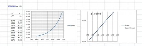
Look back at the data JhStewart9 posted for the red LED (RG71230). His data shows LED current is 0.460 mA when 1.578 volts is applied across the diode. If that is increased to 1.675 volts - which is an increase of almost exactly 0.1 volts - the LED current now rises to 9.6 mA.
Let's think about this. We've increased the voltage across the LED by 0.1 volts, and the LED current increased to almost 20 times bigger than before! It increased by nearly 2000 percent - 1987% to be exact!
In other words, the poor 12AX7 is going to try to increase its cathode current to 20 times bigger than before. This won't happen, of course; instead, anode voltage will drop to the point where the triode saturates because there isn't enough voltage between anode and cathode for it to work properly. Current won't increase 20-fold, but it will increase sufficiently to badly screw up operation of the circuit. The triode isn't able to amplify at all now - it's just sitting there, deep into saturation, with the anode at as low a voltage as it can manage to reach (probably around 100 volts DC, very roughly).
So: the simple 1.5k resistor caused a manageable 7% change in the tube operating point. The fancy red LED, on the other hand, royally screwed everything up, tried to increase triode current by nearly 2000%, and ended up making the amplifier stop working altogether. Not good!
Incidentally, what should we do if we want an even more stable result than we get with the 1.5k resistor, i.e. even less than 7% change? We actually need the exact opposite of an LED - something with a very high dynamic resistance, rather than a very low one. A constant current source would be the bee's knees, keeping cathode current exactly where we want it regardless of small changes in Vgk.
In practice, you could get absolutely superb results without going as far as a constant current source. Let's pretend you used a 11.5k cathode resistor, and connected its bottom end to a (-10 V) rail, rather than to ground (0V). The cathode rises up to the same +1.4 volts as before, which means there is 11.4 volts across the cathode resistor. Now we swap in the second 12AX7, which wants 1.5 volts instead of 1.5 at the cathode - this means there are now 11.5 volts across the cathode resistor.
We can now calculate the % change in current through the resistor. The voltage changed from 11.4V to 11.5V, across a 11.5k resistor. That means the current increased from 0.9913 mA to 1.000 mA. This is a very small change, less than 1%, only about 0.88% in fact.
And the moral of the story is: the bigger the cathode resistor, the more stable the operating point. 🙂
-Gnobuddy
Thanks for the reply.
What would cause the voltage across the LED to rise from 1.578V to 1.675V?
I think the answer is more current pulled through the LED.
However, a 12AX7 is simply not going to draw 9.6mA of Ip.
Is there a real world example of how this problem could occur in practice?
I'm thinking that a typical preamp triode common cathode stage is going to stay in class A operation, so the triode's plate current is going to stay very constant, especially in uses such as a phono preamp or the input voltage amplifier stage of a power amp. If Ip stays fairly constant, what would cause that large a voltage change across an LED as cathode load for a 12AX7?
Yes, but there's a different problem. If you put a CCS in the cathode of a triode common cathode amplifier you get no voltage gain (at the plate).
Yes, we can bypass the CCS with a capacitor. What value would that capacitor have to be? 10uF? Less? 100uF? More?
Pure theory would say that if the CCS had an AC impedance of let's say 200k ohms, then the bypass cap would only need to be 1uF or so (1uf * 200,000 ohms should yield an F3 well below 1Hz).
The standard 1.5k resistor for Rk for a 12AX7 is usually bypassed with a 22uF to 100uF capacitor. It was that way back around 1955, and still is in guitar amps. Short of a 1mA CCS bypassed by a capacitor, is Rk = 1.5k with Ck = 100uF still the best way to bias a 12AX7?
Look back at the data JhStewart9 posted for the red LED (RG71230). His data shows LED current is 0.460 mA when 1.578 volts is applied across the diode. If that is increased to 1.675 volts - which is an increase of almost exactly 0.1 volts - the LED current now rises to 9.6 mA.
Let's think about this. We've increased the voltage across the LED by 0.1 volts, and the LED current increased to almost 20 times bigger than before! It increased by nearly 2000 percent - 1987% to be exact!
What would cause the voltage across the LED to rise from 1.578V to 1.675V?
I think the answer is more current pulled through the LED.
However, a 12AX7 is simply not going to draw 9.6mA of Ip.
Is there a real world example of how this problem could occur in practice?
I'm thinking that a typical preamp triode common cathode stage is going to stay in class A operation, so the triode's plate current is going to stay very constant, especially in uses such as a phono preamp or the input voltage amplifier stage of a power amp. If Ip stays fairly constant, what would cause that large a voltage change across an LED as cathode load for a 12AX7?
the moral of the story is: the bigger the cathode resistor, the more stable the operating point. 🙂
Yes, but there's a different problem. If you put a CCS in the cathode of a triode common cathode amplifier you get no voltage gain (at the plate).
Yes, we can bypass the CCS with a capacitor. What value would that capacitor have to be? 10uF? Less? 100uF? More?
Pure theory would say that if the CCS had an AC impedance of let's say 200k ohms, then the bypass cap would only need to be 1uF or so (1uf * 200,000 ohms should yield an F3 well below 1Hz).
The standard 1.5k resistor for Rk for a 12AX7 is usually bypassed with a 22uF to 100uF capacitor. It was that way back around 1955, and still is in guitar amps. Short of a 1mA CCS bypassed by a capacitor, is Rk = 1.5k with Ck = 100uF still the best way to bias a 12AX7?
Aging tubes are like the problem with JFET Idss variability. Look up the data sheet of a JFET and you get Idss specs that are 10:1 wide. So the DIYer has to buy a bushel of JFETs in hopes that a few will have the Idss that he wants. However, resistor values are very accurate and well defined. By using a cathode resistor (source resistor) the variations in Idss or plate current is reduced by the DC negative feedback. A Voltage bias ignores the device current allowing for the device variation to potentially shift the quiescent point away from the ideal center or away from the desired idle current in an class-AB output. A cathode decoupling capacitor allows the resistor to normalize the DC current while providing a low AC impedance.
But any cathode bias in a tube amplifier output wastes a significant amount of potential output. Ok, tubes get damn hot anyway, but they do have limits and shortened lives from overheating.
I once centered the bias on a tube driver/phase splitter and got 100Watts from a "60Watt" amplifier, with no change in the pair of 6L6s. That's how crude tube amps were.
Last edited:
Why would it do that? Manna (voltage) from heaven?If that is increased to 1.675 volts - which is an increase of almost exactly 0.1 volts - the LED current now rises to 9.6 mA.
The plate-cathode voltage tends to be the grid-cathode voltage(LED, battery) times Mu. Quite stable unless there's a power grid wobble or bubbles in your battery.
...any cathode bias in a tube amplifier output wastes a significant amount of potential output. Ok, tubes get damn hot anyway, but they do have limits and shortened lives from overheating.
I once centered the bias on a tube driver/phase splitter and got 100Watts from a "60Watt" amplifier, with no change in the pair of 6L6s. That's how crude tube amps were.
Yes, that's all true for tube power amp output stages. But what about low level amplifiers, like a phono preamp or a line stage?
I'm a little disoriented here. We went from talking about cathode biasing a 12AX7 to biasing a 100 watt push-pull output stage.
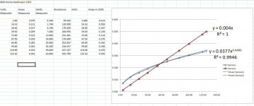
Here it is with the Exponential Trend Line. The fit is still very good.shouldn't it be exponential ...
but if you terminate the Taylor series after the 2nd order term you end up with a square law of course ...
I'd always trade some of the gain for improved linearity & operating point stability.
Just good design practice. 🙂
Attachments
The change in voltage comes from tube aging or rolling in a different tube. So diodes aren't too good for bias stability.What would cause the voltage across the LED to rise from 1.578V to 1.675V?
The tube current is roughly square law versus grid-k voltage (varying from exponential at low current up to linear at high current, like a Mosfet ) before plate N Fdbk is considered. The 3/2 law at the plate or screen grid approx. matches that 4/2 at the grid, for the Fdbk. to give an approx. linear Mu factor. (the mis-match causing the "roll-over" effect in the triode curves) So putting in a square law diode would just adjust the Mu downward (for a triode), or if slightly mis-matched from the tube characteristic, could be used to adjust the total linearity ( with a load on the plate say ). Seems like that would be a lot of work going thru umpteen diodes to get the right result, especially for an input stage where the signal is small.People talk on & on about the linearity of this or that boutique resister & than stuff in a non-linear device.
I would suggest using a Mosfet below the cathode, with a variable moderate value resistor from Drain to Gate (shunt Schaded), for adjusting the Mosfet curvature. And a variable bias voltage to the gate (thru high R ) to adjust the overall bias V. Then the overall tube stage could be linearized by adjusting the pots.
Similarly for a differential stage, an adjustable shunt Schaded Mosfet tail could be used to remove the usual 3rd harmonic dist.
Last edited:
The other way around. There is manufacturing variability between 12AX7s, as well as tube aging. If you want the same 1 mA of cathode current from any good 12AX7 you plug in, [i ]different tubes will want different Vgk. [/i]What would cause the voltage across the LED to rise from 1.578V to 1.675V?
I think the answer is more current pulled through the LED.
Similarly, as a tube ages, if you want the cathode current to stay the same, it will want different Vgk.
A cathode resistor adjusts to this situation. If its value is properly chosen, it can adjust to small changes in tube parameters. By allowing a small change in current through it, it can adjust Vgk to whatever the tube needs (Ohm's law). As we've seen, a hypothetical 0.1 volt change in Vgk results in about a 7% variation in Ia, which is manageable.
The trouble with an LED is that an LED provides "one size fits all" Vgk (equal to VLED). This results in cathode current varying much more due to inevitable tube aging and parameter spreads.
Of course not; I said as much. The point is that with LED cathode bias, normal slight variations in Vgk result in far more drastic variations in cathode current (compared to using a simple cathode resistor of the right value).However, a 12AX7 is simply not going to draw 9.6mA of Ip.
In other words, using LED bias reduces operating point stability, as I said in my first post on the subject.
Of course it is.I'm thinking that a typical preamp triode common cathode stage is going to stay in class A operation
Manufacturing variations between one 12AX7 and another, and aging. For the SAME Ip, the VGK needed is slightly different for different 12AX7s, and also changes with tube aging.If Ip stays fairly constant, what would cause that large a voltage change across an LED as cathode load for a 12AX7?
Don't fixate on the specific value I used as an example (0.1 V change in Vgk). You can do exactly the same calculations for 0.05V change, if you like, or any other reasonable value.
In every case, work through the math, putting the same change in Vgk across first a 1.5k resistor, then a red LED, and you'll come to the same conclusion every time - LED bias is far less stable than simple resistor bias.
Not a problem - use a cathode bypass cap, just as you do with a cathode resistor.Yes, but there's a different problem. If you put a CCS in the cathode of a triode common cathode amplifier you get no voltage gain (at the plate).
Exactly.Yes, we can bypass the CCS with a capacitor.
Basically, make sure capacitor reactance is no more than than (1/gm) at the lowest frequency of operation.What value would that capacitor have to be? 10uF? Less? 100uF? More?
Old tube books will have a more detailed formula in them you can use, or you can use something like LTSpice and a good 12AX7 model to simulate your circuit.
For a 12AX7 used for audio frequencies, I don't think you ever need more than 22 uF. That is enough to get you (-3dB) at around 10 - 12 Hz.
No, what matters is not the impedance of the CCS, but the impedance inside the tube as seen from the cathode. This is roughly equal to 1/gm, with the proper units. If gm is 1500 uA/V, for instance, the internal cathode impedance is around 667 ohms.Pure theory would say that if the CCS had an AC impedance of let's say 200k ohms, then the bypass cap would only need to be 1uF or so (1uf * 200,000 ohms should yield an F3 well below 1Hz).
This isn't exact (both the cathode resistor, and the tube's internal anode resistor ra, and the external anode resistor Ra, all play smaller roles). But it is close enough for all practical purposes, given normal parameter spreads in tubes and capacitor values.
Leo Fender most likely pulled that 22uF value out of the back of an RCA tube catalog, where RCA engineers had suggested values for Hi-Fi audio use. I'm sure they calculated it as well as measuring the resulting frequency response before publishing it in their catalog. For a 12AX7, 22 uF is sufficient to provide flat response well below the lowest frequency human ears can respond to.The standard 1.5k resistor for Rk for a 12AX7 is usually bypassed with a 22uF to 100uF capacitor.
100 uF is absurdly large. All it does is make the circuit unnecessarily sensitive to very low frequency noise (such as that from warped records). Bad idea.
For a guitar amp, assuming a guitar in standard tuning (no frequencies below 83 Hz), 22 uF is much bigger than needed. In fact 3.3 uF is enough for full-bandwidth bypassing, with response down about 1.5 dB at 80 Hz according to my LTSpice sim. Use 4.7 uF if you want a big fat safety margin.
Often full-bandwidth bypassing is not what you want for guitars, so the cathode bypass cap may be much smaller than 3.3uF in some designs.
Put it this way, LED bias is the worst way, from the point of operating point stability.Short of a 1mA CCS bypassed by a capacitor, is Rk = 1.5k with Ck = 100uF still the best way to bias a 12AX7?
1.5k/22 uF provides all the stability needed in practice. You can expect a few percent variation in cathode current as tubes age, or when substituting one 12AX7 for another. That is okay.
If for some (unnecessary) reason you want more operating point stability than you can get from the usual 1.5k cathode resistor, use a negative supply voltage rail and a bigger cathode resistor. The example I worked through earlier showed that a cathode resistor in the range of 10k is enough to reduce cathode current variations to under 1%, which is splendid.
Using a precise CCS really locks down cathode current, but what's the point? I consider it needless complexity with no actual benefit.
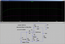
The attached image is an LTSpice sim using 1.5k/22 uF. As you can see, this provides flat response far below the lowest audible frequency (-3dB at about 12 Hz).
Note that input AC voltage is 95mV in this simulation, so the 15 dB flat top of the frequency response curve is not voltage gain. I chose that particular input voltage to set output at precisely 15 dB, so you can easily see where the curve drops below its flat-top value, and by how many decibels.
-Gnobuddy
Attachments
Are you suggesting that every 12AX7 ever made, regardless of manufacturing tolerances, regardless of tube age, always biases up at exactly the same Vgk if you plug in the typical 1.5k cathode resistor, 100k anode resistor, and 300V B+?Why would it do that? Manna (voltage) from heaven?
You know far too much to suggest that, so I must be misunderstanding what you mean.

Can you clarify what it is you are objecting to, exactly?
-Gnobuddy
I didn't. The same fundamental flaw applies to any circuit using an LED to provide small signal tube cathode bias, to power stage large signal tube cathode bias, and to JFET source bias. If someone decided to bias a BJT by replacing its emitter resistor with an LED, the same flaw applies to the BJT circuit, too.We went from talking about cathode biasing a 12AX7 to biasing a 100 watt push-pull output stage.
The flaw is very fundamental, and very basic. It comes down to this simple fact: For good operating current stability, you want a HIGH dynamic resistance at the cathode / source. An LED provides exactly the opposite, as it has a LOW dynamic resistance.
You can see this in JhStewart9's LED voltage/current data, which he so kindly provided. It takes big changes in LED current to provide small changes in LED voltage. If LED voltage is used to bias a device, then small variations in that bias voltage will cause large changes in operating current.
It happens to be the case that tubes have much less variation in bias voltage (for a given cathode current) than, say, JFETs. This lets you get away with LED bias in a tube stage, even though it is a bad design from the point of operating point stability.
-Gnobuddy
I'm reluctantly responding because I don't really want an arguement 😉. But LED biasing is essentially equivalent to fixed biasing, and in fact for that purpose the less variation in LED voltage with current the better. The tube is the device determining the current, not the LED. If you swap in different tubes you will get different currents due to tube-to-tube variability - different Ia at the same Vg, and you have no control over that (contrary to actual fixed biasing where you can adjust the voltage). The main reason people use it is to maximise gain while avoiding a bypass capacitor, so any suggestions of alternatives that require a bypass capacitor are pointless. In practise it works reasonably well unless you are relying on achieving a particular Va (i.e. for DC coupled designs). I have used them, sometimes also in conjunction with a small series resistor to provide some degeneration, but have no particular bias for against them.Just another tool in the toolbox.
There is no way in hell a 12AX7 will pass 9.6mA unless sparks are shooting out its bottom.what it is you are objecting to, exactly?
That's before we consider typical 47+k loads and <400V supplies.
I don't understand your straw-man.
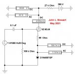
A simple diode biased voltage amp. In this simulation the diode manages to add
~0.7% distortion to the signal applied between grid & cathode.
Something to run on the bench to get real numbers.
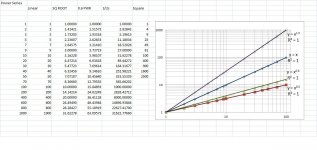
On a log-log plot some common functions become a straight line.
For example, an ideal triode forms a line with slope 3/2 while a resister has a slope of one.
Still need to put a slope of two on this for an ideal SS diode at low current tho.
Tungsten based incandescent lamps have a slope of less than one.
That is what stabilizes Wm Hewlett's version of the Wien Bridge Oscillator.
~0.7% distortion to the signal applied between grid & cathode.
Something to run on the bench to get real numbers.
On a log-log plot some common functions become a straight line.
For example, an ideal triode forms a line with slope 3/2 while a resister has a slope of one.
Still need to put a slope of two on this for an ideal SS diode at low current tho.
Tungsten based incandescent lamps have a slope of less than one.
That is what stabilizes Wm Hewlett's version of the Wien Bridge Oscillator.
Attachments
LEDs are generally used instead of silicon diodes (as you know...). For a simulated similar setup (ECC88, 27k anode resistor into a 100k load, 300V B+, 86V Va, 7.93 mA, 0.5Vrms input):
LED bias (HLMP-6000 red)
Vk = 1.762V
gain = 26.2
THD = 1.184% (2 / 3 / 4 / 5 = 1.182 / 0.069 / 0.007 / 0.001)
Resistor + capacitor (222.25 ohms // 100 uF to give same bias)
Vk = 1.762V
gain = 26.7
THD = 1.177% (2 / 3 /4 /5 = 1.175 / 0.073 / 0.008 / 0.001)
Not a lot in it....
LED bias (HLMP-6000 red)
Vk = 1.762V
gain = 26.2
THD = 1.184% (2 / 3 / 4 / 5 = 1.182 / 0.069 / 0.007 / 0.001)
Resistor + capacitor (222.25 ohms // 100 uF to give same bias)
Vk = 1.762V
gain = 26.7
THD = 1.177% (2 / 3 /4 /5 = 1.175 / 0.073 / 0.008 / 0.001)
Not a lot in it....
Of course, and I said as much - feel free to re-read that post.There is no way in hell a 12AX7 will pass 9.6mA unless sparks are shooting out its bottom.
The point is that a slight change in Vgk will try to shift the cathode current by a relatively large amount. Operating point stability is considerably worse than it is with a simple cathode resistor.
-Gnobuddy
Exactly.But LED biasing is essentially equivalent to fixed biasing
And why do amplifiers with fixed biasing almost always include some way to adjust the bias voltage? Because operating point stability is poor, and plugging in a replacement set of tubes can cause unacceptably large changes in operating point.
Which is exactly what I've been saying.
Well, no. Both tube and LED affect the operating current, of course.The tube is the device determining the current, not the LED.
Exactly!If you swap in different tubes you will get different currents due to tube-to-tube variability - different Ia at the same Vg, and you have no control over that
Better biasing schemes do indeed provide more control over that. For tubes, a simple cathode resistor works better than an LED. The four-resistor biasing circuit used in early BJT circuits (voltage divider setting base voltage, emitter resistor, collector resistor) became the standard because it provides good stability against transistor and temperature variations. The same circuit works well for JFETs. The "long tail" of an LTP provides even better bias stability, and in contemporary solid-state circuits, is combined with overall DC negative feedback to really stabilize the operating point.
In other words, LED biasing is used because people believe it is superior to using a cathode bypass capacitor. The point of my posts in this thread is that this isn't the case; in fact LED biasing trades one compromise (a bypass cap) for two worse compromises: worsened operating point stability, and increased THD. The cure is worse than the disease (which isn't a disease at all).The main reason people use it is to maximise gain while avoiding a bypass capacitor, so any suggestions of alternatives that require a bypass capacitor are pointless.
-Gnobuddy
If using an LED for cathode bias:
With low input signal levels (from tiny to about 100mV maximum), the increase in THD is likely to be tiny.
However, operating point stability is a different matter.
In the first (input) stage of a phono preamp using a 12AX7, what problems would this instability cause?
With low input signal levels (from tiny to about 100mV maximum), the increase in THD is likely to be tiny.
However, operating point stability is a different matter.
In the first (input) stage of a phono preamp using a 12AX7, what problems would this instability cause?
Yes, and the same is true for large signals too, because the dynamic resistance of the LED is always much smaller than the internal cathode impedance of the triode. To quote my book: "As is so often the case, the valve produces more than enough distortion by itself to swamp any secondary phenomena."With low input signal levels (from tiny to about 100mV maximum), the increase in THD is likely to be tiny.

Got any comparative measurements of D% to shew us? 🙂
I'd still use resister bias, that compensates for aging, PS variations & so on.
Question really becomes' Why is the maximum stage gain required'.
To me that is poor design, on the edge with no leeway for component
& ambient variation.
I'd still use resister bias, that compensates for aging, PS variations & so on.
Question really becomes' Why is the maximum stage gain required'.
To me that is poor design, on the edge with no leeway for component
& ambient variation.
- Home
- Amplifiers
- Tubes / Valves
- Some Common Diode Forward Characteristics