Quality, or type? In instrument electronics people may put carbon composition resistors in biased locations and enhance 2nd harmonic production. Fit a metal film and the result may be called more 'detailed'. Is it really more detailed? No, it just has the tonal warmth taken out.When I made my guitar pedals, their quality mattered.
Speaker crossovers don't have biased positions for doing this, and in any case are not the same. First focus on the important task of creating a good crossover.

What would a great crossover look like?
I was recommended by a friend to do a simulation through crossover simulation websites

I've never seen inductors with such small values
I was recommended by a friend to do a simulation through crossover simulation websites
I've never seen inductors with such small values
0.19 mH and 0.349 mH are not unusually small values to find in a loudspeaker crossover.
P.S. A "great crossover" is one tailored to match the individual characteristics of the drivers - something that is not achieved by using a crossover calculator such as the one above.
P.S. A "great crossover" is one tailored to match the individual characteristics of the drivers - something that is not achieved by using a crossover calculator such as the one above.
What would a great crossover look like?
A good start in gaining understanding of what makes a great crossover would be to investigate the different types of crossover filter:
https://www.audioholics.com/loudspeaker-design/filter-crossover-types-for-loudspeakers
Step 1 is to understand what is meant by the 'Q' of the filter:
Filters with a high Q introduce 'ringing' which results in poor transient response.
Step 2 is to understand the 'order' of a filter:
The order indicates the rate at which the unwanted portion of a driver's output is sloped off in order to integrate with the other drivers.
Step 3 is to understand that the filters in certain orders of Butterworth and Linkwitz-Riley crossovers create a flat voltage output in a 3-way speaker design.
P.S. Crossover design is complicated, but such basic knowledge can help one make sense of what crossover design software is actually doing! 🤓
Last edited:
Do you know of somewhere I can read and learn about it? Not about how crossovers are made or even how they work, but about capacitors, how to choose them and so on, everything, everything I know there are tables and tables about it but I would like to learn the practice of taking notes and studying more and more about them. Search with older people in my city. I see that you are a big part, not to mention all the people who respond to me here are quite experienced in this and I would like to one day reach the same level0.19 mH and 0.349 mH are not unusually small values to find in a loudspeaker crossover.
P.S. A "great crossover" is one tailored to match the individual characteristics of the drivers - something that is not achieved by using a crossover calculator such as the one above.
The books referred to earlier in this thread: Speaker Design Cookbook and Speaker Building 201 would be a good place to start.
There's not really an "ideal" crossover for a given set of drivers, it depends on what the designer wants to achieve with the sound.
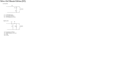
To use a simple example, here are two speakers - both apparently sound good - which use the same drivers: the Dayton DA175 and DC28F tweeter.
https://techtalk.parts-express.com/...53798-silver-al-redux?234654-Silver-Al-ReduX=
https://projectgallery.parts-express.com/speaker-projects/karma-indignia/
The crossovers are quite different.
I second Galu's comments about the sort of calculators to which you refer, they're not going to work. A crossover calculator wouldn't give either one of those speakers.
Geoff
There's not really an "ideal" crossover for a given set of drivers, it depends on what the designer wants to achieve with the sound.
To use a simple example, here are two speakers - both apparently sound good - which use the same drivers: the Dayton DA175 and DC28F tweeter.
https://techtalk.parts-express.com/...53798-silver-al-redux?234654-Silver-Al-ReduX=
https://projectgallery.parts-express.com/speaker-projects/karma-indignia/
The crossovers are quite different.
I second Galu's comments about the sort of calculators to which you refer, they're not going to work. A crossover calculator wouldn't give either one of those speakers.
Geoff
Attachments
Last edited:
Not about how crossovers are made or even how they work, but about capacitors, how to choose them and so on...
There is no mystery surrounding choosing capacitors for crossover circuits.
MKP polypropylene film capacitors are specifically designed for loudspeaker crossover networks, have excellent sonic qualities and are reasonably priced.
Expensive "audiophile" capacitors may make you feel good, just like wearing an expensive watch, but I would regard them as more for show than practicality.
Where a large capacitance value in a small physical size is required, aluminium foil bipolar electrolytic capacitors are the choice. Any reputable brand will perform well.
N.B. I would regard the actual crossover design to be far more important than the brand of capacitor used in the crossover.
Last edited:
Here's a discussion on six (yes, six) versions of a crossover for the same drivers, in this case the Dayton RS180 and RS28 MTM speakers.
Don't worry to much about the details, it will give you some idea of the complexity of this subject. The tweeters are NLA but that doesn't matter for the purposes of the discussion.
https://www.rjbaudio.com/RS180MTM/rs180-rs28-mtm.html
Geoff
Don't worry to much about the details, it will give you some idea of the complexity of this subject. The tweeters are NLA but that doesn't matter for the purposes of the discussion.
https://www.rjbaudio.com/RS180MTM/rs180-rs28-mtm.html
Geoff
Get a textbook titled AC Circuit Analysis. It doesn't much matter the author's name or the year published, they all have the same basic info about resistors, capacitors and inductors, and how they act individually and in combination in AC circuits. You may need to study DC circuit Analysis first, and learn about Kirchhoff's Voltage Law and Kirchhoff's Current Law. These will also apply to AC circuits with capacitors and inductors, though the math is more, um, complex.Do you know of somewhere I can read and learn about it? Not about how crossovers are made or even how they work, but about capacitors, how to choose them and so on, everything, everything I know there are tables and tables about it but I would like to learn the practice of taking notes and studying more and more about them. Search with older people in my city. I see that you are a big part, not to mention all the people who respond to me here are quite experienced in this and I would like to one day reach the same level
I was referring to the values of capacitors and suchThere is no mystery surrounding choosing capacitors for crossover circuits.
MKP polypropylene film capacitors are specifically designed for loudspeaker crossover networks, have excellent sonic qualities and are reasonably priced.
Expensive "audiophile" capacitors may make you feel good, just like wearing an expensive watch, but I would regard them as more for show than practicality.
Where a large capacitance value in a small physical size is required, aluminium foil bipolar electrolytic capacitors are the choice. Any reputable brand will perform well.
N.B. I would regard the actual crossover design to be far more important than the brand of capacitor used in the crossover.
You use the values plus other components that give the response you need. Obviously you need a way to know what changes these components make. You also need to know what the response is and where to take it.
Last edited:
I was referring to the values of capacitors
Calculating the value of a capacitor, i.e. its capacitance, is obviously all down to mathematics!
Let's start with a 1st order high pass filter which consists simply of a single capacitor in series with the tweeter.
The first thing to realise is that a capacitor opposes the flow of alternating current in a circuit and that the amount of opposition depends on both the capacitance of the capacitor and the frequency of the signal.
In fact, the opposition to alternating current (Xc) of a capacitor decreases with both capacitance (C) and signal frequency (f).
With me so far? 😎
The mathematical relation between the above three quantities is:
where Xc is in ohms, f is in Hz and C is in F (farads).
Now, to crossover at any given frequency, the opposition Xc should be made equal to the nominal impedance of the tweeter.
So, for an 8 ohm tweeter crossing over at 3000 Hz we have:
8 = 1 / (2 x 3.142 x 3000 x C)
Making C the subject of the equation, gives C = 1 / (8 x 18852) = 6.6 x 10^-6 F or 6.6 uF.
That's the simplest capacitor calculation you can make. I don't expect you to pursue such calculations any further. No wonder people make use of design software! 😀
You use the values plus other components that give the response you need. Obviously you need a way to know what changes these components make. You also need to know what the response is and where to take it.
It might be a bit of a crude question... But I was looking at the electrical diagrams for the crossover and I can't understand why the impedance remains the same...Here's a discussion on six (yes, six) versions of a crossover for the same drivers, in this case the Dayton RS180 and RS28 MTM speakers.
Don't worry to much about the details, it will give you some idea of the complexity of this subject. The tweeters are NLA but that doesn't matter for the purposes of the discussion.
https://www.rjbaudio.com/RS180MTM/rs180-rs28-mtm.html
Geoff
I can understand your calculations... I will studyCalculating the value of a capacitor, i.e. its capacitance, is obviously all down to mathematics!
Let's start with a 1st order high pass filter which consists simply of a single capacitor in series with the tweeter.
The first thing to realise is that a capacitor opposes the flow of alternating current in a circuit and that the amount of opposition depends on both the capacitance of the capacitor and the frequency of the signal.
In fact, the opposition to alternating current (Xc) of a capacitor decreases with both capacitance (C) and signal frequency (f).
With me so far? 😎
The mathematical relation between the above three quantities is:
View attachment 1311452
where Xc is in ohms, f is in Hz and C is in F (farads).
Now, to crossover at any given frequency, the opposition Xc should be made equal to the nominal impedance of the tweeter.
So, for an 8 ohm tweeter crossing over at 3000 Hz we have:
8 = 1 / (2 x 3.142 x 3000 x C)
Making C the subject of the equation, gives C = 1 / (8 x 18852) = 6.6 x 10^-6 F or 6.6 uF.
That's the simplest capacitor calculation you can make. I don't expect you to pursue such calculations any further. No wonder people make use of design software! 😀
In my country there are many legends and myths about audio, rude things, being more accurate using calculations helps me a lot
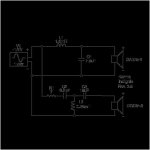
It looks similar but each is different. For example there is a peak near the woofer resonance, and a peak near the crossover.why the impedance remains the same...
When I was making the connections for my guitar sound cabinet, if I connected two 8ohm speakers in series, it gave an impedance equal to 16ohms and when I connected them in parallel, it gave 4ohms... When I see the schematic it is difficult for me to reason and think that everything would give the same impedance for all speakers (all speakers 4ohms = 4 ohms per amp).
I know I have to look at the speaker impedance graph and I also know that the impedance changes depending on the frequency of the speakers... but stillIt looks similar but each is different. For example there is a peak near the woofer resonance, and a peak near the crossover.
When I was making the connections for my guitar sound cabinet, if I connected two 8ohm speakers in series, it gave an impedance equal to 16ohms and when I connected them in parallel, it gave 4ohms... When I see the schematic it is difficult for me to reason and think that everything would give the same impedance for all speakers (all speakers 4ohms = 4 ohms per amp).
I think you may be looking at a crossover schematic and wondering why connecting an 8 ohm woofer, 8 ohm midrange and an 8 ohm tweeter together in what looks like a parallel arrangement results in a speaker system with an 8 ohm rating.
The answer to that is that the three drivers are not really electrically in parallel. The crossover divides the input from the amplifier into 3 frequency bands such that the amplifier sees a load of 8 ohm at the bass frequencies, a load of 8 ohm at the midrange frequencies and a load of 8 ohm at the high frequencies. Consequently, the amplifier sees an overall load of 8 ohm across the frequency range.
Is that helpful?
- Home
- Loudspeakers
- Multi-Way
- Solutions for different SPL between speakers