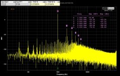
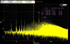
I have taken some measurements that I'd like to share. Note that I am measuring with a QuantAsylum QA403 and I have just started using it so I am getting to grips with it so take the results for what they are, I am not guaranteeing that they are correct. I am measuring using the amplifier balanced inputs. my amplifier has a 56k resistor in parallel to the negative feedback loop. Very nice linearity and harmonic decay. This amplifier sounds seriously good.
PS: the amplifier was loaded with a 8 ohm load. I am not sure that anything above 50kHz can be taken as gospel so please note.
PS: the amplifier was loaded with a 8 ohm load. I am not sure that anything above 50kHz can be taken as gospel so please note.
Attachments
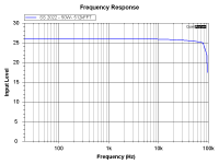
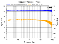
Correct. After 20 khz the analyser starts losing a little gain due to the limitation of the ADC or anti aliasing filters. See https://forum.quantasylum.com/t/amp-frequency-response-test/941. Nevertheless, an impressive analyser given the relatively low cost. Importantly it allows me to check if I have made some mistakes during the assembly process.
Soon my brother will receive the SS2022 that I made for him. Curious about his feedback, all -6dB of it (apologies for the bad joke)
Soon my brother will receive the SS2022 that I made for him. Curious about his feedback, all -6dB of it (apologies for the bad joke)
Last edited:
Can J113 be replaced with 2SK369-V? Thank you!
no, some changes are necessary, if necessary I can simulate it
no, some changes are necessary, if necessary I can simulate it
ok, you can use but reduce R23,R24from 120 to 82ohm, the bias on mosfet should be in any case about 900mA for 0dc out
Please help, what R23, R24 should I use for LSK389B used as a pair of J113?
With 120R I can see ~1V DC on outputs while 900mA idle current.
Using trimmers R25, R31 I can go lower with DC on outputs but current goes up too far.
With 120R I can see ~1V DC on outputs while 900mA idle current.
Using trimmers R25, R31 I can go lower with DC on outputs but current goes up too far.
If your current is too high when dc outputs are zero reduce the bias resistors 120ohm to 100
In any case the important is keep the current in the range 900-1000mA and both outputs to about 5-10mV
In any case the important is keep the current in the range 900-1000mA and both outputs to about 5-10mV
Last edited:
100ohm was also too high, finally I am using 75ohm as bias resistors
900mA on idle, less than 6mV on outputs (a bit floating over temperature stabilisation)
grazie mille!!!
Now the second board and the hard work to put it into the cases.
900mA on idle, less than 6mV on outputs (a bit floating over temperature stabilisation)
grazie mille!!!
Now the second board and the hard work to put it into the cases.
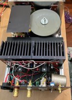
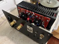
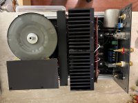
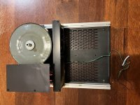
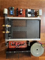
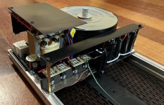
My build:
pair of monobloks, transformer on unbalanced input, LSK389 instead of pair of J113, the rest similar to the original design including soft start and DC protection. Lower voltage on end-stage, +/- 28,5 Volt.
Ugly cabling near rear panel, I know.
pair of monobloks, transformer on unbalanced input, LSK389 instead of pair of J113, the rest similar to the original design including soft start and DC protection. Lower voltage on end-stage, +/- 28,5 Volt.
Ugly cabling near rear panel, I know.
Attachments

Hi,
I have installed new PSU-boards with the MBR40250 Schottky diodes and 60.000uF per channel. See picture above.
Compared to my original build using traditional silicon recitifier bridges this verison with the schottkys sounds a lot smoother, more musical and there is no harshness whatsoever. This matches my system well since it is very neutral overall.
The main benefit using the rectifier bridges was the bass resolution and control. The bass performance with this configuration is probably the best I have ever heard in my life. If your system is overly smooth and forgiving this might be a very good choice.
/Dominic
- Home
- Amplifiers
- Solid State
- Solidstate 2022 - Hi-end amplifier