yes, these resistors create the little feedbackIsn't r3 and r16 feedback?
All those measurements with barely 60-70 dB dynamic range are pointless, they show absolutely nothing. All we know is that you have high distortion, we do not know if you have high order distortion components and we do not know if you have mains related hum components. The plots you show are in accordance with marketing plots in audio magazines.
Here the plot of thd at 18Vrms on 8ohm with -90dBAll those measurements with barely 60-70 dB dynamic range are pointless, they show absolutely nothing. All we know is that you have high distortion, we do not know if you have high order distortion components and we do not know if you have mains related hum components. The plots you show are in accordance with marketing plots in audio magazines.
It is possible to modify the harmonic decay of the distortion with a slight imbalance of the 2 feedback resistors or by using 2 less selected fet.
The peak of noise at -75dB 50Hz is a measurement problem not present on normal use.
The peak of noise at -75dB 50Hz is a measurement problem not present on normal use.

I agree...... I would say that if the majority of the THD is comprised of H2+H3+H4 (all musical) then the objectionable harmonics, H5 and beyond, are very, very small and therefore the amp should sound pretty good. The graph at #23 indicates that H5 and beyond are all below -77dB and the dominant harmonics are H2 and H3. They will mask the H5+H6+H7+..........+H20.
Tube amps have very high distortion, typically 0.5% or higher, yet people love them. I would say that people like 'effects boxes', only the technically minded go on about very low THD.
There is something about an amp presentation with low global feedback, less than 30dB. Perhaps it's distortion, but the presentation is very nice.
And as NP says, audio is entertainment, he doesn't worry too much about THD, and just hopes that everyone is having a good time..........
HD
I would say that too Hugh and I dont find anything objectionable about someone liking low order harmonic distortion. hell, I like distortion, just not typically in my amplifiers. I do find it encouraging that more people are willing o admit this penchant, rather than the time honoured tradition of inventing unmeasurable 'meta effects' to explain why the amp is superior, in spite of measuring so much worse.
it is well!!I would like to share this my new project because it sound very good and it is cheap and simple.
After the good experience made on hybrid amplifiers with circlotron configuration I thought about making a completely solid state amplifier of this type.
It is the result of many months of simulations, instrumental testing and listening test.
This is not a common solid state amplifier with lot of global feedback, there are only 6dB to reduce output impedance and to linearize the voltage stage.
You can increase the output power to 60W on 8ohm changing the chassie and increasing the power supply voltage of the output stage.
I have used the chassie HiFi 2000
Dissipante 03/300B 3U 10mm BLACK
Product Code: 1NPD03300B or 1NPD03300N
Inner baseplate for Dissipante 300mm
Product Code: 1BASEPD300
Specifications:
Pout = 50W on 8ohm with 2 x 33VDC and Vin=0.42Vrms Thd=0.6%
Pout = 90W on 4ohm with 2 x 33VDC and Vin=0.42Vrms Thd=1.3%
Pout = 18W on 8ohm no-switching with 1A bias (see simulation)
Pd = output stage at 35VDC = 70W each channel with 1A bias
Zout = 178mohm with the Exicon (see simulation)
Ft(-3dB) = DC - 2MHz at -3dB
Global feedback = 6dB
Output DC offset about 50-90mVDC (because there is no active DC servo)
These are the main characteristics:
- dc coupled of all stages
- no capacitors on the signal path
- high slew-rate
- good damping factor near to a solid state amplifiers with high feedback
- no switching output stage like a pure class A
- high efficiency because only 70W of consumption per channel
- only single ended stages
- only a single output device
- only a transconductance amplifier with I/V
- global feedback easy to modify without high frequency compensation
- full balanced circuit but it accept also un-balanced input signal
These are the components used for the pcb.
J1,J2,J3 J113D74Z
T1,T2 BC546ABU
T3,T4,T5,T6 BC556B
T7,T8 MJE340
U$1,U$2 ECW20N20-S or ECW20N20 or 2SK1058
R1,R2 100Kohm 1% 1/4W Vishay Dale RN55
R3,R4,R7 1Kohm 1% 1/4W Vishay Dale RN55
R8 500ohm 1% 1/4W Vishay Dale RN55
R5,R6 47ohm 1% 1/4W Vishay Dale RN55
R13,R14 470ohm 1% 1/4W Vishay Dale RN55
R9,R10,R11,R12 15Kohm 1% 1/4W Vishay Dale RN55
R17,R18 3900ohm 1% 1/4W Vishay Dale RN55
R15,R16 10Kohm 1% 1/2W Vishay Dale RN65
R19,R20 2700ohm 5% 2W Vishay PR02
R21,R22 2000ohm 1% 1/4W Vishay Dale RN55
R23,R24 120 or 240ohm 1% 1/4W RN55 bias 120ohm with ECW20N20
R28,R29 900ohm 1% 1/4W Vishay Dale RN55
R25,R31 1Kohm multi turn trimmer Bourns 3296W-1-501LF
RGND 100ohm 1% 1/4W Vishay Dale RN60 (not necessary for dual mono conf.)
RGROUND 10ohm 5% 2W Vishay PR02 (see photo)
C1,C2 100uF 50V UFG Nichicon
C3,C4 1uF MKP or MKT
C5,C6 not used
CIN 1uF MKP or MKT to use in parallel to R2 if only un-bal input is used
F1,F3 FUSE 5A FAST
KK1,KK4 HEATSINK SK104 13.4C/W 513002B02500G (cod. MOuser 532-513002B25G)
The connections are 63862-1 (CUT STRIP) by TE Connectivity / AMP (cod. Mouser 571-63862-1-CT, cod. RS 718-7987)
CZ 0.1uF Vishay F339X1
RZ 10ohm 2W Vishay PR02
Available the LTspice files and all the measurements with ECW20N20 and 2sk1058 .
I will make in the next days some experiment to unbalance the 2 sections to create a perfect harmonic decay like single ended amplifiers.
For me it looks a lot like the push pull tube amp design topology bought to the modern era of Solid state devices.
Minimal or no negative feedback with the euphonic sound has been the staple of tube designs.
Hopefully you are able to fully replicate that euphonic tube like sound, helps move away from tubes and stop spending ridiculous amounts of money on obsolete technology.
Keep going.
Minimal or no negative feedback with the euphonic sound has been the staple of tube designs.
Hopefully you are able to fully replicate that euphonic tube like sound, helps move away from tubes and stop spending ridiculous amounts of money on obsolete technology.
Keep going.
After the summer break I restarted the experiments on this amplifier and the listening tests with my friends.
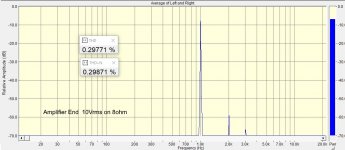
In a direct comparison with my Amplifier End which uses a tube as a voltage amplifier, an interstage transformer and the same output mosfets, the sound of this solid state amplifier remains more fatiguing.
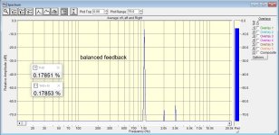
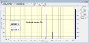
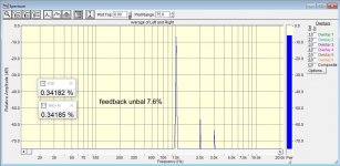
This sensation was not present in the prototype which did not have the selected fet but had a higher distortion so I tried to unbalance the 2 feedback resistors and I obtained the desired effect by increasing the second harmonic.
Follows the measurements with various values where it is verified that a small variation is enough by adding 56K in parallel to 3k9 (result 3K65) on the negative line and we obtain the same harmonic decay of the amplifer end and another listening pleasure.
In a direct comparison with my Amplifier End which uses a tube as a voltage amplifier, an interstage transformer and the same output mosfets, the sound of this solid state amplifier remains more fatiguing.
This sensation was not present in the prototype which did not have the selected fet but had a higher distortion so I tried to unbalance the 2 feedback resistors and I obtained the desired effect by increasing the second harmonic.
Follows the measurements with various values where it is verified that a small variation is enough by adding 56K in parallel to 3k9 (result 3K65) on the negative line and we obtain the same harmonic decay of the amplifer end and another listening pleasure.
Attachments

Here the final switch to modify the distortion decay
68K/56K/47K/39K in parallel to 3K9
68K/56K/47K/39K in parallel to 3K9
Attachments


This amplifier driving a 18000 euro loudspeakers, all happy of the incredible result!


Hi guys,
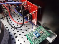
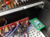
I have come quite a long way with my build. All boards are tested OK. It is time for the final assembly phase. A friend of mine works as a senior PCB CAB engineer. He was kind enough to design a board for the output stage power supply. I could not source the schottky diodes needed for rectification so I choose to use a low voltage drop rectifier bridge from Vishay along with some snubber caps.
/Dominic
Have you unbalance the feedback like I suggest ?
Are you using a custom made transformers with many secondaries ?
Hi,
Yes, R18 = 3.9k//58k
I use two custom made audio grade transformers from Toroidy. 600VA: 4x25Vac for the output stage and 40VA: 2x18+2x9Vac for the driver stage (mounted under the driver stage board).
/Dominic
Yes, R18 = 3.9k//58k
I use two custom made audio grade transformers from Toroidy. 600VA: 4x25Vac for the output stage and 40VA: 2x18+2x9Vac for the driver stage (mounted under the driver stage board).
/Dominic
- Home
- Amplifiers
- Solid State
- Solidstate 2022 - Hi-end amplifier