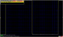

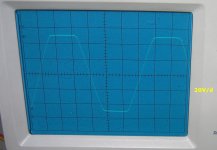
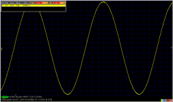
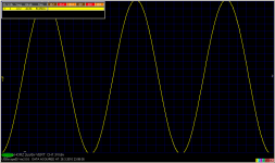
Current status - I get 180W/8R and 300W/4R from this amp with 4pairs ouf output devices.
Very nice work PMA!😉
Hugh, lanchile - thanks for your positive comments.
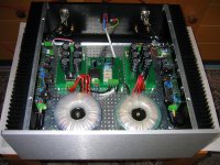
Bobodioulasso - this has been a prototype evaluation (just measurements). I am going to build the amplifier in a 4U, 440 x 400 mm box, as a dual mono. I hope to have finished this in about 2 months, and then I can say more about audible differences between smaller and bigger version.
Best regards,
Bobodioulasso - this has been a prototype evaluation (just measurements). I am going to build the amplifier in a 4U, 440 x 400 mm box, as a dual mono. I hope to have finished this in about 2 months, and then I can say more about audible differences between smaller and bigger version.
Best regards,
Pavel,
I will be most amused to see you describing the 'sound' with 'mere words'. Such an endeavour may cause great discomfort! Despite your very good English, I suspect you may have difficulties......
I know that designing a beautiful layout like yours can take 40-50 hours or more of intensive work at the CAD program. It requires great commitment and for many is dull work. You are unusual in that you have such strong technical insights but you do a beautiful, almost aesthetic layout job. I have a crazy notion that such care does improve the sound, but I could well be wrong.
Why such a tall box, 176mm is REALLY tall, would not 3U offer sufficient radiating area?
Hugh
Hi Pavel,
What can one say 🙂 an inspiration to us all surely.
And Hugh,
Quote
"I have a crazy notion that such care does improve the sound, but I could well be wrong."
Do you not find the car runs "better" and is a "better drive" when all clean and polished 😉
What can one say 🙂 an inspiration to us all surely.
And Hugh,
Quote
"I have a crazy notion that such care does improve the sound, but I could well be wrong."
Do you not find the car runs "better" and is a "better drive" when all clean and polished 😉
Hugh,
thanks again for your kind words. You are certainly right about possible difficulties resulting from describing sound.
Regarding 4U box, distance (height) between top and bottom edge of power transistors is more than 125mm. This might just fit into 3U, but ....
Supply voltage is 2 x 59V at idle, falling to some 2 x 55V at full load and power. There are 4 pairs of output devices, each biased at 25mV Re (0R22) voltage drop, i.e. 114mA / 1pair. The idle current per one channel is about 450mA. This, at 118V supply, results in 53W of idle power dissipation per channel, so large and efficient heatsinks are required.
My admiration to John Curl's JC-1. Nine pairs and much higher supply voltage ....
Best regards,
I also had quite some thermal issues to deal with - 5 pairs also at 25mV/0.22 Re. You need a big heatsink (I am using Fischer 4U case - same one I asked you about Pavel)
Very nice looking amp BTW.
Very nice looking amp BTW.
Thanks, Bonsai. Yes, the Fischer 4U is one of the candidates. I use the 3U version for the smaller amp.
Regards,
Regards,
Idle current is more than 0,5A, so I dissipate more than 60W per channel at idle. Due to large heatsinks, it makes no problem. Also, a longterm test at 30% and 50% of rated power is possible, thanks to the construction and large heatsinks. The output power I spoke about is not only a short time power.
hi
Pavel, what about bias stabylity? Do you get "constant" voltage over emiter (0.22 ohm) resistors and how much it goes over and under nominal 25mV voltage?
I hope you understood what i`ve tried to ask...
p.s. Very good fabrication and nice design!🙂
cheers Borko.
Pavel, what about bias stabylity? Do you get "constant" voltage over emiter (0.22 ohm) resistors and how much it goes over and under nominal 25mV voltage?
I hope you understood what i`ve tried to ask...
p.s. Very good fabrication and nice design!🙂
cheers Borko.
Hi Bogdan,
you are asking the right question. Yes, I do set about 26mV per one 0R22 Re resistor. It takes some time for the idle current to settle at this value, i.e. it starts at lower value after turn-on. If this were a commercial design, the thermal FB should be solved better.
Regards,
you are asking the right question. Yes, I do set about 26mV per one 0R22 Re resistor. It takes some time for the idle current to settle at this value, i.e. it starts at lower value after turn-on. If this were a commercial design, the thermal FB should be solved better.
Regards,

- Status
- Not open for further replies.
- Home
- Amplifiers
- Solid State
- Solid Solid State Power Amplifier