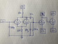
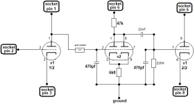
Your schematic , I’m not sure for the pins ,,, I mod it , pls tell I’m right ,that’s make sense for me
Attachments

Last edited:
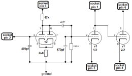
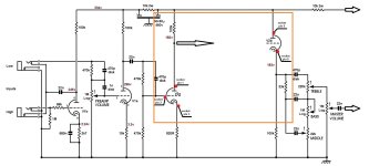
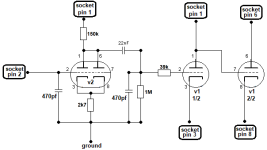
I used your nomenclature in the file.
Last gain stage and CF remains as they are. Added gain stage goes from CF power supply to ground (that’s chassis).
Last gain stage and CF remains as they are. Added gain stage goes from CF power supply to ground (that’s chassis).
yes yes you are correct... my fault sorry .. it's mine nomenclantute... so the schem is this..... i make it but without 470pf caps , beacuse i dont have now .. so i makes it and i test it and the sound have more gain but noise and buzzy.. i dont add grid resistor on the third triode.. i test it now ..
Attachments
Buzzy because of the lack of those 470p.
Which kind of noise do you hear?
Which caps value do you have in the pF and nF range that are rated at least 400V?
Which kind of noise do you hear?
Which caps value do you have in the pF and nF range that are rated at least 400V?
Good morning ,, the noise is similar like oscillator.and the frequency keeps increasing until there is a high note... only this 2 pf caps I don’t have , .. tomorrow I’m going to buy . And I tell you
if you have values close to those, use them. 330 pF or 560 pF, it’s not night and day and you could like more.
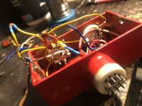
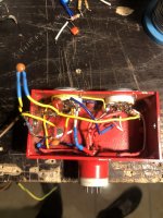
So tou have an oscillation. Post pictures of how you built it.
So tou have an oscillation. Post pictures of how you built it.
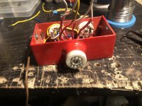
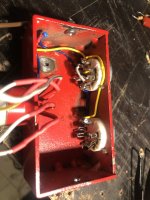
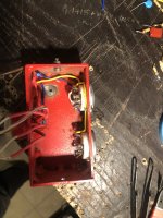
Nice home-made box!
Where do you ground the box on the amp?
For the oscillations, I’d try splitting the cables on the left and right side of the box, plus using shielded cable at input signal.
Where do you ground the box on the amp?
For the oscillations, I’d try splitting the cables on the left and right side of the box, plus using shielded cable at input signal.
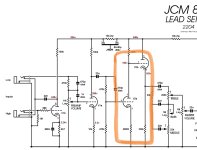
thank you . but remember its prototype .. . the second that make it work will it better....for the ground have a cable on the side of the box with a alligator clip to "bite" the amp chassis....I will try that the cables are not close to the fillaments cables....however, I see and see your design again and again and it is strange to me that the extra gain stage that I want to add is at the beginning and not in the middle of the design... you want to take a look and maybe some mistake has been made... because the truth it's that I've explained it a little strangely... I'm sending you the original design of the jcm800 and your schematic
Attachments

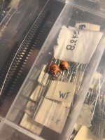
Οκ then … thanx again .. I'll buy the capacitors and I'll let you know how it works, by the way, the small classic ceramic capacitors... don't they work? I say this because I have such, but I know that they have a low volt rating
Small ceramic capacitors is what Marshall always used. 400v minimum rating. What values do you have in the hundreds of pF range?

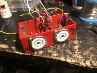
sooooooooo. i make some change to solve the oscilation.. i change the 47k anode resistor with 100k. and i add on the grid of third gain stage 39k - 100k and 330k ... and nothing... so im thinking to change the anode of the valve 2 from pin 6 to pin 1 . to take the current from the 1st socket stage and BOOM.. its work!!!!!! no oscilations .. now i rebuild again. to see the results
yes .. after a lot test with resistors . fouund the right point for me.. (the plate resistor on second valve is 100k the 150k make the sound more deep fuzzy )
tomorrow i send here and demo sound with stock jcm800 and adapter on it... really thank you zintolo
tomorrow i send here and demo sound with stock jcm800 and adapter on it... really thank you zintolo
Attachments
- Home
- Live Sound
- Instruments and Amps
- Soldano hot mod v2 on oscilloscope