Any of the usual suspects -PCD7/8, LspCAD 6.0, VituixCAD 2.0, SoundEasy, XSim, Boxsim will model series crossovers.
If you can draw a series crossover schematic on paper, you can also do it in XSim. If not, google for a series crossover and copy it.
Ralf
Ralf
Well, think about it logically & you'll figure it pretty quickly: ask yourself where the 'ground' normally goes? Not graphically in terms of the usual electrical ground symbol -where does it physically go?
No: think first. That way you'll have a better understanding. I'll ask again: if you have a [passive crossover] circuit, where does the ground actually lead to? Doesn't matter if it's series or parallel. If you answer that, you'll have answered your own question.
Last edited:
I'm sure, but what good does spoon-feeding do? If you figure it for yourself (it's a simple one) you'll have a much better idea about how it works.
Think. Those little ground symbols you draw on a crossover circuit diagram. When you build the crossover -where do they go? Do they just disappear into the aether? Or do they, just possibly, connect to something?
Think. Those little ground symbols you draw on a crossover circuit diagram. When you build the crossover -where do they go? Do they just disappear into the aether? Or do they, just possibly, connect to something?
Jeff Bagby produced a table of filter values that give good impedance some years back. But I can't locate it right now.
The Third order one was for 8 ohm drivers:
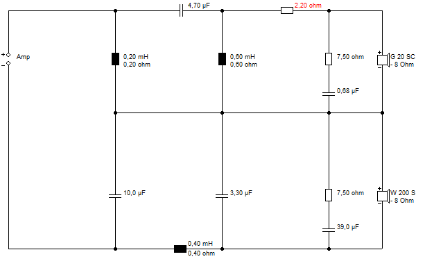
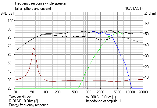
This sort of speaker:

Flat Impedance and Flat Power response design.
The drivers are impedance corrected. Notice the 3:2:1 ratio of values. Can't remember if I time aligned the model. Bafflestep is what always messes these things up from the ideal. But looks good to me.
Software | Visaton
The Third order one was for 8 ohm drivers:
This sort of speaker:
Flat Impedance and Flat Power response design.
The drivers are impedance corrected. Notice the 3:2:1 ratio of values. Can't remember if I time aligned the model. Bafflestep is what always messes these things up from the ideal. But looks good to me.
Software | Visaton
You do not need to use the ground symbol in Xsim. It is optional, and it just simplifies the more complicated circuits so that the wires are not crossing. You shouldn't need it for a basic series crossover.ok
in xsim i am not able to connect the ground,
Jeff Bagby's Series Crossover Designer and Passive Crossover designer do series xo's. Need Excel for them to work.
ok guys, someone of you has developed series crossover with xsim ?
if yes could post an example of it ?
thank you
if yes could post an example of it ?
thank you
HiFi Loudspeaker Design
A calculator for series filters. I have some other info that I can post when at home.
HiFi Loudspeaker Design
A calculator for series filters. I have some other info that I can post when at home.
HiFi Loudspeaker Design
Last edited:
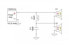
'post an example ': took about a minute
although I don't know why you'd bother:
Series vs. Parallel Crossover Networks
although I don't know why you'd bother:
Series vs. Parallel Crossover Networks
Attachments
- Home
- Loudspeakers
- Multi-Way
- software for series crossover calculations