'post an example ': took about a minute
although I don't know why you'd bother:
Series vs. Parallel Crossover Networks
This is a 1st order serial filter (6dB) and S1 is the tweeter and S2 the Mid/woofer.
You should impedance linearize the woofer with a Zobel, and you need to be carefull not cross the tweeter too low. If the fs on the tweeter is 500 Hz, you would want to cross around 3-4 KHz. And that means that the woofer has to go quite high too. If they cant, you will need a higher order crossover.
It is almost invented in my backyard (Dynaudio) They used those filters most of the time in their older speakers.
They should be phase linear, and they ´distribute´ the whole signal, so that you will not get any positive/negative peaks at the cross over frequency.
You would also want to use a tweeter LCR resonance filter to get the most out of it.
ArthurDK, you should look in more often. Broken Dynaudio speakers continue to baffle and bewilder us! We could do with enlightenment. 😀
Tandberg of Norway were always big on series filters too:

Not saying the Tandberg HiFi 15 was any good, of course. But decent Celestion and SEAS drivers IIRC.
Mr. Troels Gravesen was very scathing about this piece of series crossover nonsense:

Worst thing he ever heard.
Tandberg of Norway were always big on series filters too:
Not saying the Tandberg HiFi 15 was any good, of course. But decent Celestion and SEAS drivers IIRC.
Mr. Troels Gravesen was very scathing about this piece of series crossover nonsense:
Worst thing he ever heard.
Serial filters can turn out awful, but then you have to redesign them 🙂 I did talk to Gravesen years ago, and at that time he didn´t fancy them at all, but then again at that time he didn´t think that capacitors had any impact on the sound either 🙂
I also thought that if a speakerwire is thick enough, it will give a good sound. And that is proved wrong, so we all have the right to change our minds.
I have designed 5 speakers with serial filters, all sounding very good, but with a lot of time in between, so that I have forgot the reasoning behind the design.
There is a Dutch guy who really are into serial filters, and it should be possible to google him.
In the AR schematic R1 is an attenuation and C1 determines the crossover FR for the tweeter. L1 and L2 determines the crossover FR for the woofer. I am not sure why he split split L into 2 coils.
But then again I am no expert, I just wanted to help the thread owner a little bit along the way.
We had a loudspeaker engineer many years ago, Peter Holm, he would have made an impedance linear attenuation directly on the tweeter instead of R1.
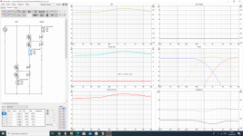
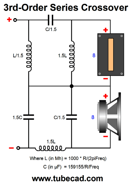
i want represent this scheme of 3rd order series filter in xsim:
for example this is the ground on parallel xover:
but for series 3rd order (don't care about components values) what is the correct ground?:
1)
2)
3)
😕
for example this is the ground on parallel xover:
but for series 3rd order (don't care about components values) what is the correct ground?:
1)
2)
3)
😕
Last edited:
1) is the correct way.
3) works also but is an illogical way to depict it.
Remember, there isn't a ground in AC, you use the ground symbol in the parallel crossover as an aid in designing it, but you don't have to either.
Ralf
3) works also but is an illogical way to depict it.
Remember, there isn't a ground in AC, you use the ground symbol in the parallel crossover as an aid in designing it, but you don't have to either.
Ralf

1) is the correct way.
3) works also but is an illogical way to depict it.
Remember, there isn't a ground in AC, you use the ground symbol in the parallel crossover as an aid in designing it, but you don't have to either.
Ralf
Dead right, Ralf.
You are going too fast in multiple directions for me diypass. I had to bail there. 😱
Firstly, there is no such thing as a Ground in HiFI. Most domestic amplifiers have no Earth connection at all. The Earth is just the chassis connection for safety. Saves you from Electric Shocks.
We do, however use a reference point on Voltage. In the Pro World, people use balanced line, which has a centre Voltage.
I really don't want to go into a deeply technical subject about common-mode and differential mode.
Both can work well, when properly designed.
Now I have no idea what John Devore does in his designs, beyond him being a very clever bloke:
But he doubtless impedance corrects his drivers. One being a Morel CAT 378:
MOREL CAT 378 Soft Dome Horn Tweeter – AmpsLab
Thing is. Not many drivers sound good on low-order crossovers. But occasionally do.
- Home
- Loudspeakers
- Multi-Way
- software for series crossover calculations