ble0t said:I just noticed I never added an LED to this to signal if it has been turned on i.e. RL3 has closed. I'll add that early next week and then look at doing a very small run of boards (4 or 5).
Hi, look forward to seeing final version w/ led and hopefully place an order for two.
Spotted the test pads for the accessory board which would probably work out quite well for Brian's 'Prox' touch sensor. I remember Maxhawk used this 'attached' momentary switch for his boards which might be quite nice, looks like they have a low profile fit.
Stan
Attachments
1000 uF for the DC blocking is a bit small. I would suggest 4700-10000 uF. This is of course dependent of max primary current.
OK...I think I have the size at 13mm diameter, so I should be able to find a larger cap in that range that will fit. Thanks for the advice 😉
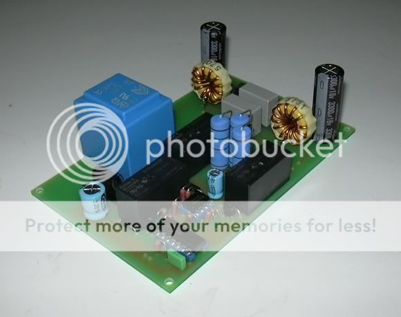
Well, I got a couple boards made for a few little projects I was working on, and I included this one. Here's a shot of the completed board. The parts for it come in tomrorow, so hopefully I can post a fully stuffed shot tomorrow night. And sorry about the glare/bad quality...I don't have a real up-to-date digital camera 😉
Hi,
It's not the lack of an up to date digital camera that's the problem.
It's the location of the flash.
Choice; either switch off the flash and use daylight or use 2 flash located either side of the camera and arrange for the reflections to miss the camera lens. Usually if the flash are about the same distance from the lens as the lens is from the object will achieve this.
Daylight illumination is simpler.
Don't blame the equipment.
Trick: Don't have the board towards the camera, angle it a bit in order to avoid the reflexions or take it outside!
OK....I think I did a better job this time around 😎
This should be a nice addition to my forthcoming leach clone 😀
This should be a nice addition to my forthcoming leach clone 😀
Hi All,
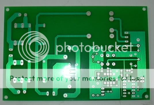
sorry to barge in onto this thred, but I just designed my first PCB based on the circuit posted in post #6 (first page of this thread)
since it is my first real PCB design, i would like some of You to have a look at it.
the power resistors are mounted off the board, this leaves all possibilities open (heatsink mounting etc..)
I only added connections for one powerline, the other needs to be connected directly.
240V part is separated by a ground plane on the PCB, i don't know if this is necessary, but it makes me feel better..
the circuit is powered with 12 Volts, power supply is a separate PCB
many thanks in advance
Regards Robin
sorry to barge in onto this thred, but I just designed my first PCB based on the circuit posted in post #6 (first page of this thread)
since it is my first real PCB design, i would like some of You to have a look at it.
the power resistors are mounted off the board, this leaves all possibilities open (heatsink mounting etc..)
I only added connections for one powerline, the other needs to be connected directly.
240V part is separated by a ground plane on the PCB, i don't know if this is necessary, but it makes me feel better..
the circuit is powered with 12 Volts, power supply is a separate PCB
An externally hosted image should be here but it was not working when we last tested it.
many thanks in advance
Regards Robin
Hi,
is there another mains switch before the soft start?
Then this switch must (in the UK) switch both the neutral and the live.
If the soft start relay is your only mains switch then the first relay should not be parallel connected and you should run the neutral and live to the two halves so that both poles are being used separately.
The gap from PCB fixing to the live input seems a bit small. No metal bolts here, use only plastic (nylon) fixings. Your track gaps look OK on the mains side. How about adding a mains fuse on the PCB?
Hi,
just noticed that the K2 unused poles are close to the ground protect track. What is the gap?
Q what gap do you need, 1.6mm?
just noticed that the K2 unused poles are close to the ground protect track. What is the gap?
Q what gap do you need, 1.6mm?
There is a fused mains switch that disconnects both lines.
but maybe it would be better to disconnect both lines using the relais.
the unused pads of the relais are never high, so the gap is not that important i think.. it is 1.5 mm by the way..
thanks for Your feedback
but maybe it would be better to disconnect both lines using the relais.
the unused pads of the relais are never high, so the gap is not that important i think.. it is 1.5 mm by the way..
thanks for Your feedback
ah, good point, didn't noticed that..
I changed the layout to accomodate other relay types.
all gaps between the 220V lines are 2mm or more
thanks
I changed the layout to accomodate other relay types.
all gaps between the 220V lines are 2mm or more
An externally hosted image should be here but it was not working when we last tested it.
thanks
Good idea, thanks.
I've been staring at the thing for a long time to eliminate the jumper, but didn't see it..
I also did some more fine tuning
here's the latest version
I've been staring at the thing for a long time to eliminate the jumper, but didn't see it..
I also did some more fine tuning
here's the latest version
An externally hosted image should be here but it was not working when we last tested it.
- Status
- Not open for further replies.
- Home
- Amplifiers
- Solid State
- Soft start & Soft Switch circuit: can anybody help?