I have just bought the attached circuit from a German firm named THEL. The quality is fantastic, maybe a little expensive, but this circuit is just what I needed... at least this what I thought!
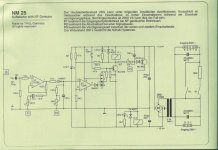
Depending on the position of the J1 switch, this circuit behaves in the following ways:
Pin 2-3 shorted: simple softstart. The soft start duration is determined by a trimmer
Pin 3-4 shorted: the circuit is activated by an external signal (0.2 mV to 2mV, sensitivity set by trimmer), cycles through the soft start time and then stays on. After an adjustable period from the last signal received (1-10 minutes, set by a trimmer), the circuit turns off.
Pin 1-2 shorted: the circuit behaves like a soft switch activated by the S1 switch. Therefore, when S1 is closed the soft start cycle starts and the circuit is activated until S1 is opened again.
I have a problem with the last way of working: I didn't understand that the circuit operated based on a switch (i.e. permanent contact), I thought it operated based on a button (i.e. a momentary contact turns on, another momentary contact turns it off).
I definitely need the circuit to work with a button. Can anybody tell me if there is a way to modify the circuit in order to implement this feature? Help please!
Attachments
Hi,
you need a latch.
Add a third relay in parallel to K1.
After the button is pressed both K1 & K2 come on. K1 starts the timing period and things work as designed. K3 output contacts are wired in parallel to S1. K3 will now hold BC879 on and maintain voltage to the timer even after you release S1.
A comment on the design if I may. K1 & 2 are wired to hold in on full voltage for the whole listening period. They will run pretty warm and the extra K3 will also do likewise. Select a suitable relay and make sure the enclosure is well ventilated. Even better if you could modify the circuit so that each relay receives a higher voltage pulse & then holds on with a reduced voltage, usually about half to two thirds rated voltage.
Check my logic before you implement!!!!
I understand the latch principle, but how do you turn the whole thing off? Can it be done by pressing again the same button?
I'll check the temperature of the relays after a few hours, and I'll let you know.
I'll check the temperature of the relays after a few hours, and I'll let you know.
Hi,
try to find the recent thread (maybe 4 or 5 weeks ago) that showed a schematic for latching and unlatching using a push to make unlatched button.
I'm going to do a search under my name, see who finds it first.
try to find the recent thread (maybe 4 or 5 weeks ago) that showed a schematic for latching and unlatching using a push to make unlatched button.
I'm going to do a search under my name, see who finds it first.
Hi,
found it. A lot older than 5 weeks.
You might want to read the whole thread.
http://www.diyaudio.com/forums/attachment.php?s=&postid=577870&stamp=1108675104
found it. A lot older than 5 weeks.
You might want to read the whole thread.
http://www.diyaudio.com/forums/attachment.php?s=&postid=577870&stamp=1108675104
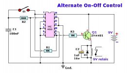
somebody posted this circuit here - I cannot remember who, apologies for not giving proper credit. you could build the flip flop portion on a small proto board and connect the output to the end of the switch that connects to the base of the BC879.
Attachments
In the end, I've made the circuit Kristjan designed (see attachment), but I can't get the relay to switch.
Everything seems to work fine, when I connect a LED instead of the relay it works fine, the tension measured at the poles of the relay (without the relay in place) is 8.3V
I wonder if the transistor can't provide enough current for exciting the relay. If this is right, how can I solve the issue?
Please bear in mind that all the components work fine, I've already changed them at least once!
Thanks for any help!
Attachments
perhaps a silly question, but is the relay rated for 9V operation?
How much current does it draw? If it is within the limits of the pass transistor, you might try reducing the 10K resistor to permit more base current and therefore more current to the relay. You may also want to try connecting two of the pass transistors as a darlington pair for more current.
What happens to the 9v supply voltage when you try to activate the relay?
What voltage do you get at the relay terminals when you try to operate it?
The supply is oversized, I've operated the relay by tapping it directly into the regulator's output without any problems. In this configuration it draws 50mA approx.
Based on what I know about the transistor, it shoud be able to operate it without any problems. However, when I measure the voltage with the relay in place and the circuit activated I find only 2.5V.
I've also tried to measure th current flowing to it and it's 16mA approx., way too low.
I've tried lowering the resistor feeding into the transistor, but with 5K (instead of the original 10K) I get only 19mA
Can I put 2 transistors in parallel? Alternatively, how much can I dare lowering the resistor?
I have assembled this circuit, and had the same problem initially. I found out I had my collector and emitter reversed 
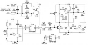
Also, I've been working on a combination momentary switch + soft start circuit (based on Rod Elliotts P39 and the momentary toggle circuit posted above). Here's the schematic if anyone is interested (sorry if it's a tad sloppy).
EDIT: Beaten to the punch by SY 😉
Also, I've been working on a combination momentary switch + soft start circuit (based on Rod Elliotts P39 and the momentary toggle circuit posted above). Here's the schematic if anyone is interested (sorry if it's a tad sloppy).
EDIT: Beaten to the punch by SY 😉
Attachments
switch + start circuit...
Hi, yes definitely interested, looks like a good one to crack my knuckles with my Eagle lite program.
Stan
ble0t said:I have assembled this circuit, and had the same problem initially. I found out I had my collector and emitter reversed
Also, I've been working on a combination momentary switch + soft start circuit (based on Rod Elliotts P39 and the momentary toggle circuit posted above). Here's the schematic if anyone is interested (sorry if it's a tad sloppy).
EDIT: Beaten to the punch by SY 😉
Hi, yes definitely interested, looks like a good one to crack my knuckles with my Eagle lite program.
Stan
Member
Joined 2002
m.parigi said:In the end, I've made the circuit Kristjan designed (see attachment), but I can't get the relay to switch.
Everything seems to work fine, when I connect a LED instead of the relay it works fine, the tension measured at the poles of the relay (without the relay in place) is 8.3V
I wonder if the transistor can't provide enough current for exciting the relay. If this is right, how can I solve the issue?
Please bear in mind that all the components work fine, I've already changed them at least once!
Thanks for any help!
Exactly.. Im building these too. But the transistor he used is to little for the current.
Why use relay, does any one try its hands on TRAIC BTA41 40A 600V Power triac using a random tun-on optocoupled traic driver ++ other circuits also.... to Soft start, because relays have the tendency of contact-bounce, arching and contact sticking......
I have seen these traics offering softstart to 4kW Magnetic Induction Welding machines.
I have seen these traics offering softstart to 4kW Magnetic Induction Welding machines.
here is a link to application note.......a little bit comlex circuit for newbies but could be altered to simple working.....http://www.edn.com/contents/images/112201di.pdf
As you said a bit complex besides how good is it using traic's for high fidelity?
BTW: I checked your homepage Kanwar and I see that you like IGBT's. Quite odd since the rest of the world has dismissed this type of transistor. I have no opinion really because I have never come near that part.
BTW: I checked your homepage Kanwar and I see that you like IGBT's. Quite odd since the rest of the world has dismissed this type of transistor. I have no opinion really because I have never come near that part.
peranders said:As you said a bit complex besides how good is it using traic's for high fidelity?
BTW: I checked your homepage Kanwar and I see that you like IGBT's. Quite odd since the rest of the world has dismissed this type of transistor. I have no opinion really because I have never come near that part.
The Traic is meant to used in series of primary winding of supply transformer, and i have seen many professional amplifiers[mine included] using traics for soft start. They are more reliable than relays and produce no mechanical noise and when they are turned fully on they doesnot deteriorate the waveform.
Regarding your misconception towards IGBT, we are not alone in this world using IGBT's in amps, there are many high end reference amplifier manufacturing companies using IGBT's in their amps , though i donot remember their name at this moment, use these devices.................
We implement IGBT's from APT , which are new generation devices which donot suffer from second breakdown voltages and are much more reliable than their older versions such as Toshiba IGBT's................for more information kindly visit www.advancedpower.com for more clarifications.
post 11...
Hi ble0t,
Did you find the OPA131 a complimentary replacement for the uA741 that Rod uses or was it a conveince from your library (the pins are the same) to be replaced later?
Stan
Hi ble0t,
Did you find the OPA131 a complimentary replacement for the uA741 that Rod uses or was it a conveince from your library (the pins are the same) to be replaced later?
Stan
- Status
- Not open for further replies.
- Home
- Amplifiers
- Solid State
- Soft start & Soft Switch circuit: can anybody help?