Member
Joined 2002
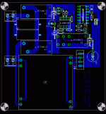
ble0t said:I whipped up a layout yesterday...it comes in around 3.75" square, which isn't too shabby. I need to tidy things up a bit, but I thought I'd post it to get some feedback. Thanks in advance...
I like this.. want to share the files ?
Member
Joined 2002
ble0t said:Sure...I'll post the .brd file tomorrow...I have that project on my work comp 😉
Sweet thanks. 😀 you can email it to me if you want. 😀
J'
ble0t, I like your project a lot! It's much more compact than the board I purchased.
Can you please let us have the components' values and some specs?
Thanks!
Can you please let us have the components' values and some specs?
Thanks!
Here's the .brd file for it...I cleaned up the silk layer and a couple little things.
As for the values / specs, they are identical to those in the schematic in post #7 of this thread and to ESP Project #39. The one difference is that I only had room to use two limiting resistors in the soft start circuit, so you would probably want to increase the size/wattage of these two as compared to the project.
As for the values / specs, they are identical to those in the schematic in post #7 of this thread and to ESP Project #39. The one difference is that I only had room to use two limiting resistors in the soft start circuit, so you would probably want to increase the size/wattage of these two as compared to the project.
Attachments
HI,
how about radial power resistors to save space?
240v mains require about twice the resistance. Does that means twice the power dissipation?
how about radial power resistors to save space?
240v mains require about twice the resistance. Does that means twice the power dissipation?
That sounds like a good suggestion...I could definitely give that a shot. Thanks!
As for 240V mains...currently, the primary side of the transformer is wired for 120V operation, although I could add some jumpers to make it switchable between the two.
I'll work on it a bit over lunch and hopefully have an updated version later today 😀
As for 240V mains...currently, the primary side of the transformer is wired for 120V operation, although I could add some jumpers to make it switchable between the two.
I'll work on it a bit over lunch and hopefully have an updated version later today 😀
Anyone use one of these before?
http://www.crydom.com/userResources/productFamilies/54/crydom_sst.pdf
From digikey with the relay:
http://www.digikey.com/scripts/DkSearch/dksus.dll?KeywordSearch
about $68US. Looks like you'd need a cheapo transformer and a bridge to get the control voltage, which would also allow a small power switch. Probably $5 total in additional parts.
Looks interesring.
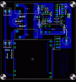
ble0t said:And the .brd file for anyone interested...
ble0t,
Definitely interested, watching, saving and enjoying.
Thank you.
Stan
Member
Joined 2002
I guess I should add that I used the Schrack RT series relays in the design on this. I've used them before in other projects, and they work well and are compact for their ratings. They are available at Mouser.
BrianDonegan: Interesting...seems to be a based on a solid state relay? I suppose you'd just need to design the switch circuit to close an additional relay that would apply the necessary control voltage. Not a bad setup 😎
BrianDonegan: Interesting...seems to be a based on a solid state relay? I suppose you'd just need to design the switch circuit to close an additional relay that would apply the necessary control voltage. Not a bad setup 😎
I was thinking something as simple as this (see pic). The transformer wouldn't need to be anything special, just a tiny cheapo EI. And the switch wouldn't be loaded at all really. You could tap off the 12V for an LED as well.
EDIT: Oops, fixed digikey link: http://dkc3.digikey.com/PDF/T052/1306.pdf
EDIT: Oops, fixed digikey link: http://dkc3.digikey.com/PDF/T052/1306.pdf
Attachments
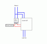
BrianDonegan: Are you using a momentary switch in your design? If so, it doesn't seem like that would work...it needs constant DC voltage to operate. Also, it seems like you'd need a really small secondary voltage on that transformer to not exceed the 10V maximum of the control voltage. I think digikey has some Amveco ones with 6VAC secondaries though...
Nope, a regular SPST toggle switch. For the transformer, I was thinking of one of these: MT7249-ND (2V x 2 = 4V). I know I put 12V, but I am working and writing this at the same time.
http://dkc3.digikey.com/PDF/T052/1428.pdf
http://dkc3.digikey.com/PDF/T052/1428.pdf
Even better than the Amveco 😉
Seems like your solution would work fine...I just like having a soft switch 😀
Seems like your solution would work fine...I just like having a soft switch 😀
ble0t said:
Seems like your solution would work fine...I just like having a soft switch 😀
Any place for an LED?
If you are going to order some of these bds for yourself and others, count me in! I believe these are single sided for etching your own as well?
A BOM would be great for the footprints and reccomendations for IC1,IC2,Q1,Trans, relays and radial res. recommendations for people like me who just fell off the diy truck.
Best - Stan
- Status
- Not open for further replies.
- Home
- Amplifiers
- Solid State
- Soft start & Soft Switch circuit: can anybody help?