Something is wrong.
You should not be reading 130Vac or similar when first connecting and not when it is controlled to OFF.
Disconnect from the mains, disconnect from the transformer.
report the measurements I suggested.
You should not be reading 130Vac or similar when first connecting and not when it is controlled to OFF.
Disconnect from the mains, disconnect from the transformer.
report the measurements I suggested.
Thanks Andrew. The measurement you suggested, is it with the Soft Starter standing alone and not connected to transformer/condenserbank?
Eivind S
Eivind S
yes, completely disconnected.
We need you to confirm the correct purpose of each input connector. Then we can advise on how to wire it up.
We need you to confirm the correct purpose of each input connector. Then we can advise on how to wire it up.
The unit I tested yesterday has stopped working. No click, no red led light when the momentary switch was activated.
Luckily I have a newer version very simular with a three legs led instead of a two legs red.
No mains power connected:
Between the two N terminals: O.L Between the two L terminals 0 ohm.
Mains power ON but momentary switch OFF:
Between the two 220 V in: 230V AC Between the two 220V out: 230v AC
The red led light up.
Momentary switch ON:
Between the two 220V in: 230V AC Between the two 220V out:230V AC.
The green led lights up. I can both hear/ feel the relay click with my finger tip.
The momentary switch OFF:
The red led lights up. A new click from the output relay was heard/felt
230v AC on both 220V in and out.
I will wait until Andrews comments to connect this unit to the V3 power unit.
Eivind S
Last edited:
since that circuit is isolated from mains, you can test it for function....
mine is the forum soft starter ckt....
surely the traffo provided will have its primary dc resistance in the near thousand ohms.
can be on all the time. as long as the IEC mains connectors are plugged in....
didn't that come with documentation? i will not buy anything
without proper documentation so buyers beware....
i think all information is in your post #1....
you should be able to use this board......
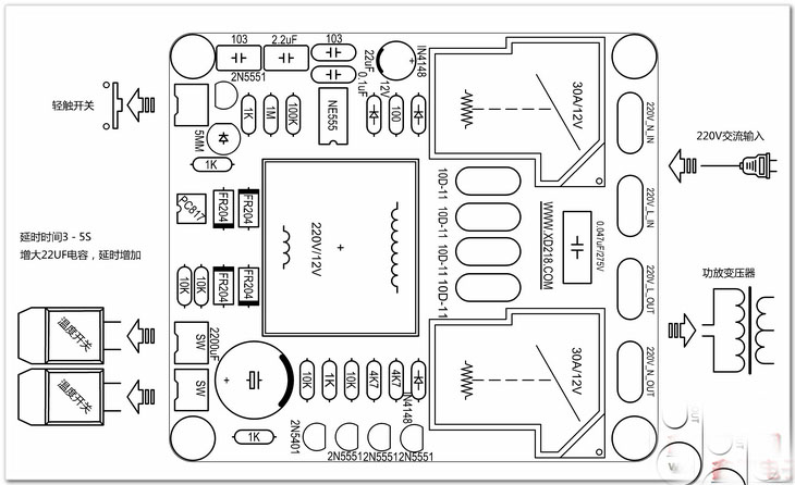
in your ebay board one relay shorts out a bank of NTC's
while another relay opens the circuit in case of thermal overload,
this is the reason for two relays...2 heat sensors one for each channel
sink....
so one relay is operated normally open while the other is normally closed
found this in the net.....the difference is there is a delay from the time you push the switch, about a second, to the closing of the normally open relay....almost instantaneous.....
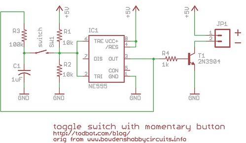
the unit is wired this way.....
you should be able to use this board......
in your ebay board one relay shorts out a bank of NTC's
while another relay opens the circuit in case of thermal overload,
this is the reason for two relays...2 heat sensors one for each channel
sink....
so one relay is operated normally open while the other is normally closed
found this in the net.....the difference is there is a delay from the time you push the switch, about a second, to the closing of the normally open relay....almost instantaneous.....
the unit is wired this way.....
What was the resistance between Live and Live, when all was disconnected?
AJT,
the earlier posts had virtually agreed that the first relay was to allow remote low voltage power ON. And the second relay was for the soft start to bypass the added resistance.
AJT,
the earlier posts had virtually agreed that the first relay was to allow remote low voltage power ON. And the second relay was for the soft start to bypass the added resistance.
I see a 555 timer on the sheet.
So you apply mains and nothing happens. You then short the contacts and the unit operates...
Then what ? Do have to remove the mains input to reset back to off or does the momentary switch (yes that's what that symbol seems to show) turn the unit off ?
I would also as a safety precaution make sure that the momentary contacts are isolated from the mains. Is that a mains transformer in the middle powering it all ?
with isolation transformer used, the momentary, normally open switch is in no danger of causing shocks......i have some....
Attachments
Its a while since I posted that 🙂
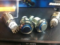
I seem to recall just needing to be sure the OP's board was fully isolated with there being no circuit diagram shown. Those are quite good switches, officially anti vandal proof I think 😀 The illuminated ones are great.
I seem to recall just needing to be sure the OP's board was fully isolated with there being no circuit diagram shown. Those are quite good switches, officially anti vandal proof I think 😀 The illuminated ones are great.
What was the resistance between Live and Live, when all was disconnected?
0 ohm.
Eivind S
That means the connections are wrong, or that the added resistances have failed to zero ohms, or the bypassing relay is welded closed.
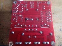
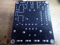
You will have to look under the PCB and see where the Live traces go. They should pass through the added resistances.
Last edited:
that's the way to do it, look at the copper side to trace the circuit,
removes the guesswork once and for all....
i have strong hunch the other relay disconnects the power
trafo when high temp is sensed at preset temps....
removes the guesswork once and for all....
i have strong hunch the other relay disconnects the power
trafo when high temp is sensed at preset temps....
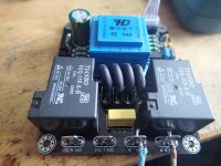
The first photo is from the copperside of the "first" unit identical to the photo brought in the first post in this thread. Why this unit stopped to function after beeing connected to the transformer/powerbank of V3(Aleph J), I have no idea.
The second and third photo is the "newer version" taken from both sides. All measurement I brought in post 24 is taken from this unit(black).
The reason that resistance between the two L terminals = 0 ohm, is that they are connected to the same pad on the PCB
The second and third photo is the "newer version" taken from both sides. All measurement I brought in post 24 is taken from this unit(black).
The reason that resistance between the two L terminals = 0 ohm, is that they are connected to the same pad on the PCB
Attachments
is the added resistor in the Neutral line?
Do you remember I asked
Do you remember I asked
You are not doing yourself any favours, by ignoring help after you asked.Disconnect all terminals, no power !
Measure the resistance between the two Neutral terminals.
Measure the resistance between the two Live terminals.
"You are not doing yourself any favours, by ignoring help after you asked".
Andrew, I do not understand why you are saying this.
What help have I ignored?
I have tried the best I could to follow your advise doing the measurement I presented in post 24. There could be something I have misunderstood, but that is something very far from ignoring.
The resistance measurement you aked for was of course with no power connected.
"is the added resistor in the Neutral line"? Have any words fell out here, it does not give any meaning to me.
If you, Andrew, feel that you, for reasons I do not understand, cant help,I hope that other members can. It is wise to have in mind the fact that English is not my mother tongue.
Eivind S
AJT
Have you studied the photos of the copper side. Did the photos "clear up" how this slow start work?
I have worked with other other soft starts before, but they cut 230V AC when the main switch is OFF,but with this unit 230 V AC can be measured on both 220V in and out all the time.
I assume that this kind of unit is used in TV (etc), where you activate full power using a remote. But using such a unit in a classe A amplifier with a high current runing all the time, I am not sure it is a "good idea".Don you have any comments on that?
Eivind S
do you have a normally open momentary switch like the one i showed?
are the thermal sensors connected? these should be in circuit to make
the board function as it should...
are the thermal sensors connected? these should be in circuit to make
the board function as it should...
Thank you AJT.
Yes, I use a momentary swicth exactly like those you show in your picture.
No, so far I have not connected the termal senors. I will try that tomorrow and with the transformer and condenserbank to the Aleph J (V3) also connected.
Eivind S
Yes, I use a momentary swicth exactly like those you show in your picture.
No, so far I have not connected the termal senors. I will try that tomorrow and with the transformer and condenserbank to the Aleph J (V3) also connected.
Eivind S
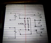
this is the power line side arrangement in your board,
it will show you how soft start is implemented....
so two relays operate in sequence,
when powering up, one after the other....
but when powering down, they turn off at the same time,
same with thermal cut-off, when preset temp is
detected, the 555 timer is toggled off...
two relays are de-energized....
Attachments
- Status
- Not open for further replies.
- Home
- Amplifiers
- Power Supplies
- Soft start question