Oop's, here is the sch to match the top silk and the top asy as well.
Thank you for your helpfulness but you seem to have missed the point of the thread.
The enquiry was about the use of reactance to limit the current rather than a resistance. Your material would be better suited to a different thread.
Best wishes
David
Transformers have dual primaries for either 117V in parallel or 234V in series so they can be connected for either. On the secondary side I have two center tapped windings for the output stages and two for the input stages along with a 12V winding for the housekeeping circuit.
Good Listening
Peter
Good Listening
Peter
Maximum inrush current for a large transformer core occurs when it is switched on at the zero crossing point. Lowest inrush current occurs when power is applied at the peak of the cycle... counter intuitive but that's the way it is.
This idea seems to have started from Rod Elliot's website. He is usually very informative but I think this one is incorrect.
The idea seems to be that an inductor driven by a sine wave potential has the peak current when the sine wave potential crosses zero.
This is true only of the steady state condition and does not apply to the initial transient solution.
This is classic maths that you can check but the intuitive explanation is simple.
When the source is connected at the time the potential is zero then there is obviously no current flow. As the potential increases the current will then increase. Toni's link supports the idea, as far as my Deutsche can tell.
One complication is if the transformer core was left partially magnetized because the power was cut under load. The transformer may draw increased current if the remnant field is in the reverse direction to the reconnection.
I have never seen data on this. I should be able to calculate the approximate size of the effect but it depends on the core material.
This was one of my questions. Anyone have data or calculations on this?
Self claims the inductive component is usually more than the power supply capacitor inrush but provides no data and it doesn't look correct to me.
Cordell's picture on p355 shows the capacitor load clearly and the inductive inrush is not evident, but it may be off scale, so still not proof.
Best wishes
David
Last edited:
(10A). You would really have to flick the switch fast - only stays warm for a couple hundred milliseconds.
This would do ...
http://www.farnell.com/datasheets/87339.pdf
A read of your posted data sheet shows the thermal time constant as 245 seconds.
A lot more than your claimed "couple hundred milliseconds"😉
They work anyway, but I want to do better.
Best wishes
Dear David,
you would need a big capacitor for startup. Think of secondary side - the big electrolytics which are initial a short circuit ...
I calculate about 3 to 12 uF should do it in a second or two. Not bad.
Tell me if I miscalculated.
Using a zero cross detector solid state relay maybe is also an option which I have thought about some months ago. Have already bought a bunch of S216S02 (16A/250VAC) for testing. But don't think that zero crossing and shorting the cap would work.
Why not?
The zero current release of most SSRs would also prevent any transformer core remnant field and subsequent inductive inrush, so that is another reason they appeal to me. Was this part of why you purchased them?
Best wishes
David
Last edited:
I calculate about 3 to 12 uF should do it in a second or two. Not bad.
Tell me if I miscalculated.
Why not?
The zero current release of most SSRs would also prevent any transformer core remnant field and subsequent inductive inrush, so that is another reason they appeal to me. Was this part of why you purchased them?
Best wishes
David
Dear David,
this is one of the reasons why I bought SSR's for testing but don't know if it helps to avoid the magnetization which occurs on switch off the transformer...
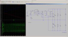
Attached you can find a simulation of a 650VA Transformer using a 3µ cap. What we can not simulate is the inrush current phenomenon but we can get some information about capacitor load.
Don't know if this ~300 mA current helps here to premagnetize the core to avoid the big inrush current. Maybe you are able to test this (wearing safety glasses)?
(R1, R2, R3 is the dc resistance of the windings.)
BR, Toni
Attachments
I had a think about this and it probably doesn't.this is one of the reasons why I bought SSR's for testing but don't know if it helps to avoid the magnetization which occurs on switch off the transformer...
If the transformer is not turned off under load then it seems that would help.
This stuff is not intuitive to me.
Attached you can find a simulation of a 650VA Transformer using a 3µ cap. What we can not simulate is the inrush current phenomenon but we can get some information about capacitor load.
Don't know if this ~300 mA current helps here to premagnetize the core to avoid the big inrush current. Maybe you are able to test this...
Thanks for the simulation. The transformer inductances are determined from measurements or what information?
12uF for 2 seconds should put the rails near 50V. About what I expected and should be OK.
The idea to pre-magnetize the core is the plan of WWW.EMEKO.DE.
Seems like they are real experts but probably makes more sense to you, only some parts are translated.
I had the idea to charge the supply capacitors with a series of little pulses only as a way to avoid the capacitor load inrush. The fact that it can also avoid the inductive inrush never occurred to me until I read the EMEKO website.
I have not yet my toroidal transformers to test this, but hopefully not too far.
Your recommendation of eye protection is wise😉
In the meantime I welcome any ideas or data.
Best wishes
David
Last edited:
...
The idea to pre-magnetize the core is the plan of WWW.EMEKO.DE.
Seems like they are real experts but probably makes more sense to you, only some parts are translated.
...
The emeko.de link seems to be broken. Here a detailed description in english:
http://www.emeko.eu/uploads/media/HWA-Beschreibung-e.pdf
Very clever - seems to be patented.
Using a microcontroller and a triac or SSR's without zero detection (think I have bought the wrong ones
 ) it would be no big problem to premagnetize the core - without using a resistor and/or capacitor ...
There is some information what causes the magnetization => turn off during load!
BR, Toni
Last edited:
The emeko.de link seems to be broken...
I don't understand, the link works when I click on it.
But the website doesn't seem to work very well.
I will try the Sprachauswahl: EMEKO, Michael Konstanzer site and see if it is better.
Thanks for the information, I hope the products are better than the translation.
... a microcontroller and a triac or SSR's without zero detection ... without using a resistor and/or capacitor
Yes, this occurred to me. But a capacitor is very robust and almost fool proof.
The EMEKO solution is very nice but I am not sure if I want the complexity.
Perhaps it is just unfamiliarity that makes me cautious.
Best wishes
David
Last edited:
... a microcontroller and a triac or SSR's without zero detection...
Hi Toni
I have had time to think about this and I am now more comfortable with the idea.
Even if there is a failure then the circuit will not overheat, much better than the resistor solution and a little cooler than the thermistor.
Better than either if there is a very short power interruption and a restart.
Requires only low power parts, not power resistors with usually unspecified pulse power capacity.
OK.
I don't think it even needs a micro-controller. Just a simple circuit to ramp up the time that the TRIAC is switched on until it is full on.
Each pulse cancels any remnant field from the previous cycle so no inductive inrush.
This is different from the EMEKO idea but should work well.
Make sense?
I wonder if there is a need to short out the TRIAC to avoid any non-linearity near crossover. Would a small snubber capacitor do the job?
Also to repeat my earlier question - where did your values for the transformer primary inductance come from? I don't have a toroid handy to measure this.
Best wishes
David
Last edited:
Hi Toni
I have had time to think about this and I am now more comfortable with the idea.
Even if there is a failure then the circuit will not overheat, much better than the resistor solution and a little cooler than the thermistor.
Better than either if there is a very short power interruption and a restart.
Requires only low power parts, not power resistors with usually unspecified pulse power capacity.
OK.
I don't think it even needs a micro-controller. Just a simple circuit to ramp up the time that the TRIAC is switched on until it is full on.
Each pulse cancels any remnant field from the previous cycle so no inductive inrush.
This is different from the EMEKO idea but should work well.
Make sense to you?
I wonder if there is a need to short out the TRIAC to avoid any non-linearity near crossover. Would a small snubber capacitor do the job?
Also to repeat my earlier question - where did your values for the transformer primary inductance come from? I don't have a toroid handy to measure this.
Best wishes
David
Dear David,
have a look at my circuit. First we switch on mains with master relay. Triac control now starts to ramp up the voltage for the toroids in between about 10 mains voltage cycles. Afterwards triac will be shorted by the second relay to avoid any triac switching artefacts. We only remove the resistors and replace them by the Triac.
As there is no big current flowing through the relays during switching the relays may live forever ... 😉
BR, Toni
have a look at my circuit. First we switch on mains with master relay. Triac control now starts to ramp up the voltage for the toroids in between about 10 mains voltage cycles. Afterwards triac will be shorted by the second relay to avoid any triac switching artefacts. We only remove the resistors and replace them by the Triac.
As there is no big current flowing through the relays during switching the relays may live forever ... 😉
I can't see any circuit yet but the description is more or less what I proposed.
The relays should be under no stress and will last well. I only wonder if we even need to short the TRIAC - any crossover artefact will occur when there is minimal current anyway because the load is rectified capacitors.
Have you, or anyone else, seen data or have experience with this?
Best wishes
David
Dave, I seem to have missed your reply from the 12th Aug.
Maximum inrush currents on toroids really do occur when the power is applied at the zero crossing but that statement needs qualifying because of course if the voltage is zero no current can flow.
I struggled to find anything that easily shows this but eventually turned this up. Have a look at figure 3. As you correctly say, residual core magetism plays a big part too.
http://www.ee.ktu.lt/journal/2011/0...s of Transformer and Operating Conditions.pdf
Maximum inrush currents on toroids really do occur when the power is applied at the zero crossing but that statement needs...
I realized a bit later what you probably meant was -
"Maximum inrush currents on toroids occur if power is applied at the zero crossover".
It doesn't occur "when the power is applied".
D'accord?
The EMEKO documentation say that even that is not actually correct for toroids, more accurate for transformers with lower remnant flux like E-I cores, news to me but doesn't affect my idea.
Thanks for the link, I will read it.
Best wishes
David.
The EMEKO info really says the converse - that minimum inrush occurs if power is applied at the peak is not true for toroids. Should have been more careful in my words.
Last edited:
I can't see any circuit yet but the description is more or less what I proposed.
The relays should be under no stress and will last well. I only wonder if we even need to short the TRIAC - any crossover artefact will occur when there is minimal current anyway because the load is rectified capacitors.
Have you, or anyone else, seen data or have experience with this?
Best wishes
David
Dear David,
the circuit as shown in post #9...
Triac-experience: about more as 30 years ago I build a 3 channel audio controlled light organ based on triacs ... 😉
Dear David,
the circuit as shown in post #9...
Triac-experience: about more as 30 years ago I build a 3 channel audio controlled light organ based on triacs ... 😉
OK. simple and fine, but I meant the circuit for the TRIAC control.
Your previous experience will help with that aspect, but I also meant experience or data about the effect of the TRIAC crossover non-linearity on audio circuitry - EMI?
SSRs are used quite a bit, mostly not bypassed AFAIK. Maybe it is OK to simplify even further and eliminate one relay?
[more than 30 years? Your enthusiasm made me think you not so old as that😉]
Best wishes
David
I ... eventually turned this up. Have a look...
OK, had a look. Consistent with my earlier comment that what you wrote was incorrect but it supports what you probably meant. Nice to clear that up if it was just miscommunication.
The article discusses remnant field in Webers/coil. Awh, it's late here, do I have to convert that into teslas and...?
Have any data on typical toroid number of turns, primary inductance etc.?
Best wishes
David
...
OK. simple and fine, but I meant the circuit for the TRIAC control.
Your previous experience will help with that aspect, but I also meant experience or data about the effect of the TRIAC crossover non-linearity on audio circuitry - EMI?
SSRs are used quite a bit, mostly not bypassed AFAIK. Maybe it is OK to simplify even further and eliminate one relay?
...
A snubber combination accross SSR pins is required by datasheet and will minimize EMI. Maybe the second relay can be eliminated - OTOH we are able to eliminate SSR EMI if we short circuit the SSR after toroid startup is complete.
BTW: The simulation data I have posted before show by hand measured resistance and inductance values.
Thanks!...
more than 30 years? Your enthusiasm made me think you not so old as that
...
BR, Toni
A snubber combination accross SSR pins is required by datasheet and will minimize EMI. Maybe the second relay can be eliminated - OTOH we are able to eliminate SSR EMI if we short circuit the SSR after toroid startup is complete.
Yes a relay is a certain fix for the EMI, but with a SSR for short circuit protection it is a temptation to eliminate all the nasty contacts😉
I suppose a few FETs with sufficient Breakdown V. could be found to do the job.
The trade-off in on resistance would not be critical.
BTW: The simulation data I have posted before show by hand measured resistance and inductance values.
Thanks. I asked about that earlier but you may have missed it, so I wanted to check.
Best wishes
David
- Status
- Not open for further replies.
- Home
- Amplifiers
- Solid State
- Soft start. A (new?) idea and a few questions.