Thank you for your effort.
At DIYINHK under the page for the usb card it specified that at 16/24 bit 192Khz sample the BCK is 12,28 Mhz.
Here is a pic (sorry for the bad quality) from my messure at the input of the isolatior ic on the dam1021.
It was at around 2,3 Mhz and it looks like a valid datastream. One thing i notice is that it's a kind of weak signal (i think).
The scope say 307mV.. Can that have something to do with it?
Again, thank you all for helping.
Regards //Daniel
At DIYINHK under the page for the usb card it specified that at 16/24 bit 192Khz sample the BCK is 12,28 Mhz.
Here is a pic (sorry for the bad quality) from my messure at the input of the isolatior ic on the dam1021.
It was at around 2,3 Mhz and it looks like a valid datastream. One thing i notice is that it's a kind of weak signal (i think).
The scope say 307mV.. Can that have something to do with it?
An externally hosted image should be here but it was not working when we last tested it.
Again, thank you all for helping.
Regards //Daniel
I don't see a problem with the bitrates, but the ~300mV levels do not look OK to me. The Si8620 isolator needs at least 800mV to register a "high" on its inputs.
If I were you I'd make the same measurements with the USB interface disconnected from the Soekris, to see if the voltage levels return to proper values.
If I were you I'd make the same measurements with the USB interface disconnected from the Soekris, to see if the voltage levels return to proper values.
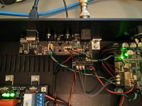
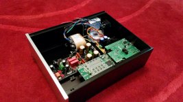
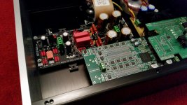
I finished my s/pdif inputs board and installed it in my Soekris:
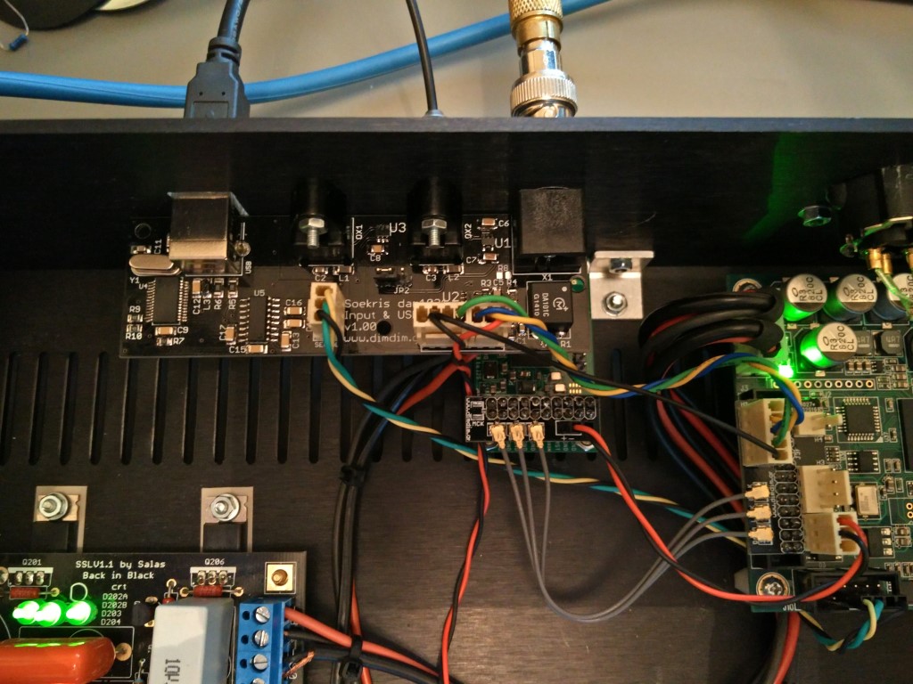
I decided to include two toslink inputs instead of one, and LDOs for powering the toslinks and the coax input. I also included a USB-to-RS232 circuit, to minimize fuss with performing firmware updates.
While I was at it, I also made small adapter PCBs with U.FL sockets for the Soekris, the DIYINHK XMOS interface and the Amanero.
Schematics, PCBs and BoM will become available when I find some time to do it right.
Attachments
Dimdim - saw the post on your site about the board - very nice. Have to summon the courage to attempt soldering those fine-pitched SMDs!! I did my Soekris optical and coax inputs on perf board but your board looks elegant. As a quick aside (sorry Daniel), BigGLT's 'any Apple remote' code seems to run afoul of the tighter compiling rules of the 1.6.6 Arduino IDE. My sketch based on his and your code runs fine if installed with 1.06 but the IR doesn't work when compiled and installed with 1.6.6. My version using your 'paired' remote code works fine on 1.6.6. Have to spend some time debugging.
Daniel, as suggested earlier you should reflash the firmware/filters and start from scratch again. Can you try another i2s source like an RPI? Or try an SPDIF source?
Daniel, as suggested earlier you should reflash the firmware/filters and start from scratch again. Can you try another i2s source like an RPI? Or try an SPDIF source?
Last edited:
So, it was a no go again. I tried most of what i have stuff for.
First, the weak signal from usb card was my bad. I had the probe at x10 😱
I have tried a Luckit waveIO card from my TDA1541 dac, but the same result. A strong input (from both usb cards) with alomst the same kHz/MHz on BCK and LRC. Datastream look similar too what i can see.
I tried to force the input with cables connected to ground and to inputselect.
But still no lock and nothing comes out.
Best regards //Daniel
Did you get a chance to look at the serial port's output?
No, i don't have a working usb/serial cable yet. I Think it will arrive next week.
Regards //Daniel
1) it's from external PS and spot on 3.3v
2) the Sorkris isolator are powered with 3.3v at J3 pin 6 and 7
3) yes, the are standard 10cm cables.
Daniel,
it seems you're powering the isolators at wrong pins (6=gnd 7=spdif_in+)
The right pins are 13 & 15. RTFM 😉
Let us know if it works now.
Last edited:
Hello, thank you. Yes, it was a typing error, i'm using pin 13 and 15.
I have rechecked my connections and can't find anything wrong.
I order my card in november so if Soekris homepage are correct my card should be updated to fw 0.99. I have been suggested to update again, i haven't done that yet, still waiting for the usb/r232 cable. What file should i upload? I downloaded 3 diffrent files.
I will report if this solwed the problem as soon as i get the cable...
Best Regards //Daniel
I will report if this solwed the problem as soon as i get the cable...
Also measure voltage and current from the power supply to the DAM. Current should be ~160 mA from V+ and 50-60 mA from V-.
The DAM will blink, but won't lock when supplied with insufficient current.
What PS do you use?
I'm using a 2*12v 6VA transformer, connected to a standard 7812/7912 pcb. The DC is at the Soekris input spot on +/- 12v.
I have borrowed a usb/r232 converter and will try to update tonight.
Best Regards //Daniel
I have borrowed a usb/r232 converter and will try to update tonight.
Best Regards //Daniel
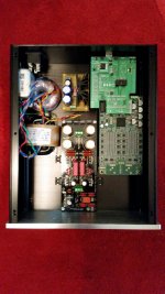
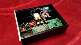
So what do y'all think about this layout?
The basic setup is as follows: dam1021 rev.2 with a DCB1 for power, output buffer and mute, a diyinhk XMOS USB receiver and normundss' input switch board.
For info on the DCB1 see http://www.diyaudio.com/forums/blogs/tea-bag/296-salas-hot-rod-dcb1.html should you not be familiar with it already.
On the mains side there'll be a fused power receiver with a DPDT switch (in the pics there's just a fused receiver though), a line filter (EVOX, rated 3A), a 30VA 2x12VAC R-core transformer for the DCB1, and a toroid with 2x6VAC. To power the switch board I'll be using the 2x6AC toroid and a nice LM317 prereg which will be going to the output tab of the 7805 on the input switch board, effectively bypassing the 7805.
The dam1021's raw output will go into the DCB1 buffer, the input impedance of which I've set to about 20k. The buffer sports a muting relay, so that's taken care of. The shunt regulator of the DCB1 will also be supplying the dam1021 with 10V of the finest DC. The regulator's CCS is set to about 500mA, about twice of what's needed. The RCA output connectors will be located just above the input switch board.
I thought I'd run the layout by you folks before I start drilling. So waht do you think?
Attachments
If you want to bypass the 7805 and use your own 5V regulator, you will need to disconnect the 7805 output pin from the PCB. I have just uploaded an updated document with details on various supply scenarios, check the "Using external 5V supply with onboard 3.3V regulator" section. Link to the doc is in the first post of the GB thread.To power the switch board I'll be using the 2x6AC toroid and a nice LM317 prereg which will be going to the output tab of the 7805 on the input switch board, effectively bypassing the 7805.
Since you don't seem to have anything that actually requires a 5V supply, another option might be to build your LM317 regulator for 3.3V output and bypass both onboard regulators.
If doing the 16-cap mod (4x per phase) how small does the leads going through the vias need to be? Or rather how large (AWG) wires can go through them without any trouble (solid leads that is).
- Home
- Source & Line
- Digital Line Level
- Soekris' DAC implementations